Vehicle-mounted hydraulic constant speed power generation system

A power generation system and hydraulic technology, applied in the field of hydraulic system, can solve the problem of inconvenient heat dissipation, and achieve the effect of simple structure and good shaking off

Pending Publication Date: 2018-12-18
张家港韶液液压技术有限公司
View PDF1 Cites 1 Cited by
  • Summary
  • Abstract
  • Description
  • Claims
  • Application Information

AI Technical Summary

Problems solved by technology

[0002] In order to generate a power supply with stable voltage and frequency, the vehicle-mounted generator needs to keep the constant speed of the generator. After searching, the authorized announcement number is CN205173100U. A vehicle-mounted hydraulic constant-speed power generation system, including a variable pump and an external charge pump in series. The hydraulic pump set is connected to the on-board engine for driving, and the hydraulic pump set is also connected to the generator set. The generator set is composed of a constant-speed hydraulic motor and a permanent magnet generator. The generator set is connected to the useful electrical equipment through the inverter. The variable variable pump and the constant speed hydraulic motor form a closed hydraulic system, which has the characteristics of simple manufacture, reliable performance, small appearance, light weight, driving or parking power generation and high power generation quality, but its generator set is used for a long time Afterwards, a large amount of heat will be generated, which is not easy to dissipate, so we propose a vehicle-mounted hydraulic constant-speed power generation system to solve the above problems

Method used


Image

  • Vehicle-mounted hydraulic constant speed power generation system
  • Vehicle-mounted hydraulic constant speed power generation system

Examples


Embodiment Construction

[0018] The technical solutions in the embodiments of the present invention will be described in detail below in conjunction with the accompanying drawings in the embodiments of the present invention. Obviously, the described embodiments are only some of the embodiments of the present invention, not all of them. Based on the embodiments of the present invention, all other embodiments obtained by persons of ordinary skill in the art without making creative efforts belong to the protection scope of the present invention.

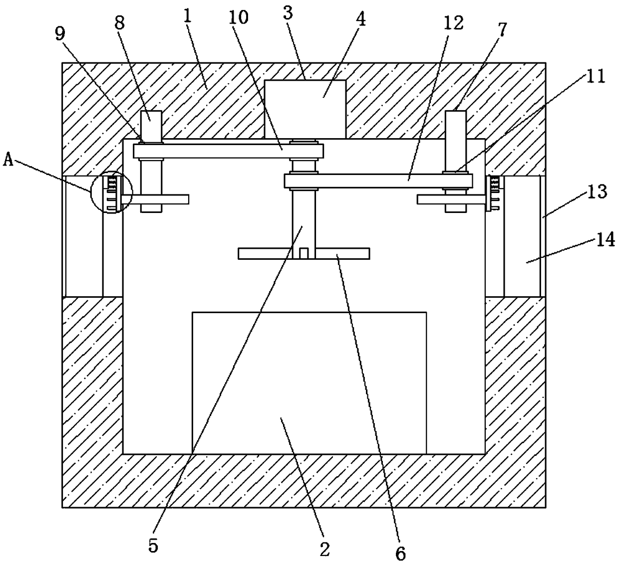
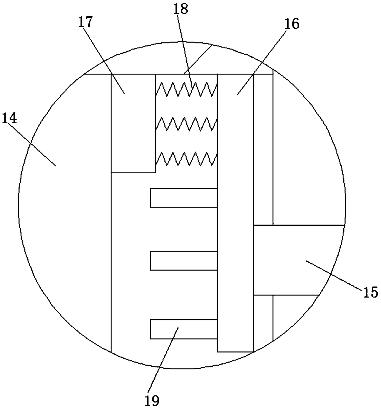
[0019] refer to figure 1 with 2 , a vehicle-mounted hydraulic constant-speed power generation system, comprising a storage box 1, a generator set 2 is fixedly installed on the bottom inner wall of the storage box 1, an installation groove 3 is opened on the top inner wall of the storage box 1, and a rotating motor is installed in the installation groove 3 4. The output shaft of the rotating motor 4 is welded with a rotating shaft 5, and a plurality of fan blad...


PUM


Abstract

The invention discloses a vehicle-mounted hydraulic constant speed power generation system which comprises a placing box. A generator set is fixedly installed on the bottom inner wall of the placing box. A mounting groove is formed in the top inner wall of the placing box. A rotary motor is mounted in the mounting groove. A rotating shaft is welded to an output shaft of the rotary motor. A plurality of fan blades are fixedly mounted on the outer side of the rotating shaft. Two rotating grooves are formed in the top inner wall of the placing box. Spindles are mounted into the rotating grooves in a rotating mode, and the outer side of the rotating shaft and the outer side of one of the two spindles are fixedly sleeved with first chain wheels. The outer sides of the two first chain wheels areengaged with one same first chain. The outer side of the rotating shaft and the outer side of the other one of the two spindles are both fixedly sleeved with second chain wheels. The vehicle-mountedhydraulic constant speed power generation system is simple in structure, economical and practical, and the generator set can be subjected to heat dissipation treatment through the rotating shaft and the fan blades. Moreover, dust on a dust screen can be well shaken off through moving plates and rubber pillars, and the phenomenon that influences, caused by blockage of the dust screen on the heat dissipation efficiency is avoided.

Description

technical field [0001] The invention relates to the technical field of hydraulic systems, in particular to a vehicle-mounted hydraulic constant-speed power generation system. Background technique [0002] In order to generate a power supply with stable voltage and frequency, the vehicle-mounted generator needs to keep the constant speed of the generator. After searching, the authorized announcement number is CN205173100U. A vehicle-mounted hydraulic constant-speed power generation system, including a variable pump and an external charge pump in series. The hydraulic pump set is connected to the on-board engine for driving, and the hydraulic pump set is also connected to the generator set. The generator set is composed of a constant-speed hydraulic motor and a permanent magnet generator. The generator set is connected to the useful electrical equipment through the inverter. The variable variable pump and the constant speed hydraulic motor form a closed hydraulic system, which...

Claims


Application Information

Patent Timeline
IPC IPC(8): F15B21/04
CPCF15B21/042F15B2211/62
Inventor 刘双全
Owner 张家港韶液液压技术有限公司
Why Eureka
Try Eureka