Dust removing powder material drying box

A technology for powder materials and drying boxes, which is applied in drying, drying machines, drying solid materials, etc., and can solve problems affecting the life of components in the drying box, powder falling out, and prolonging drying time.

Inactive Publication Date: 2018-12-18
应娉
View PDF5 Cites 2 Cited by
  • Summary
  • Abstract
  • Description
  • Claims
  • Application Information

AI Technical Summary

Problems solved by technology

Due to the simple internal structure of the traditional electric blast drying box, the usual practice is to put the powder material in a container such as a tray or a basin and then put it in the drying box for drying. This method cannot achieve uniformity of the powder material. heat, prolong drying time
Therefore, in order to speed up the drying process, the operator needs to turn the powder material frequently. During the turning process, the powder will fall out, resulting in a lot of dust in the drying box, which will affect the life of the components in the drying box.

Method used


Image

  • Dust removing powder material drying box
  • Dust removing powder material drying box
  • Dust removing powder material drying box

Examples


Embodiment 1

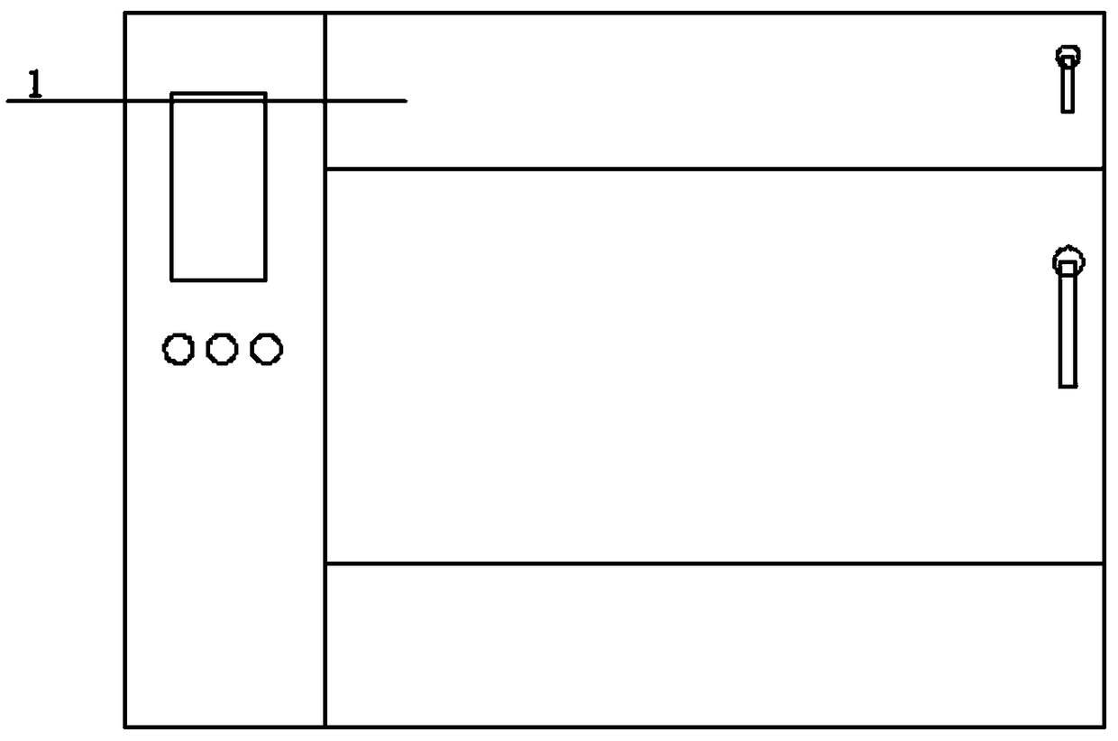
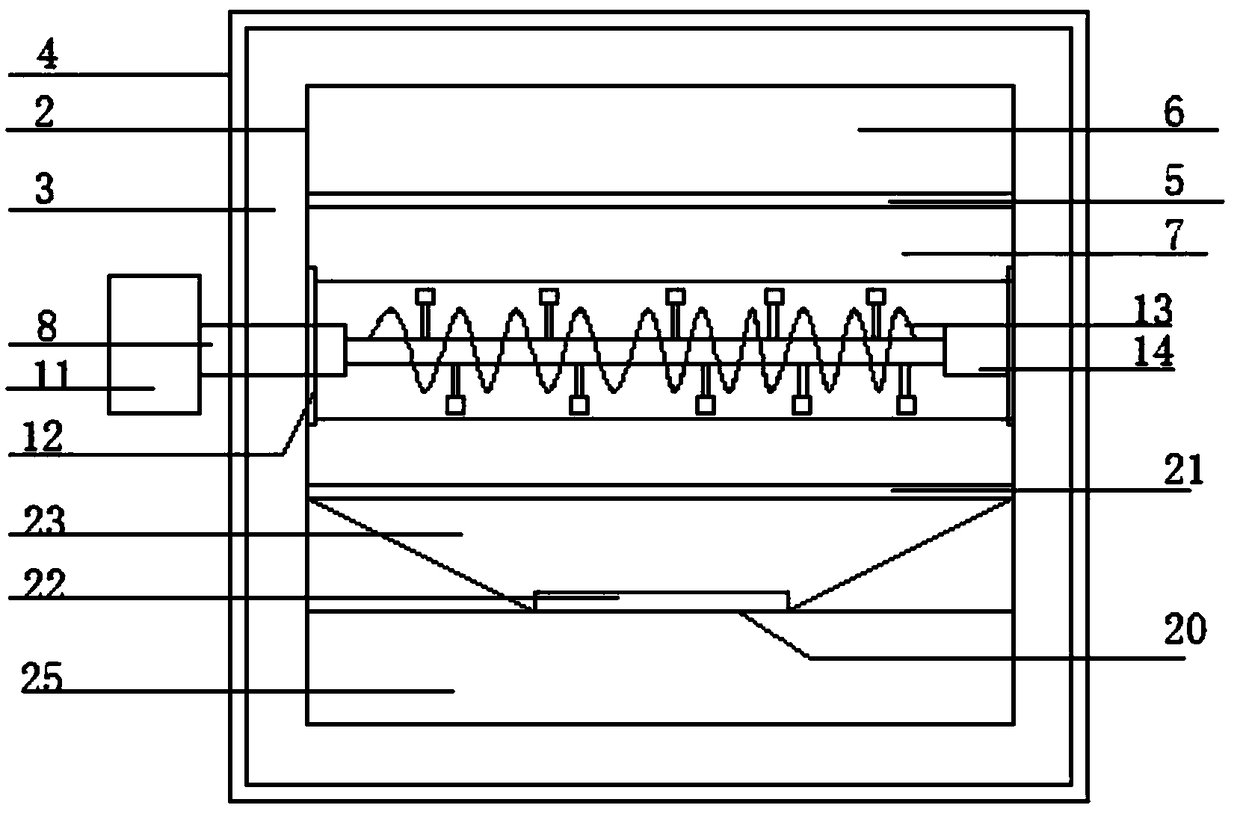
[0029] Such as figure 1 As shown, a dust removal powder material drying box includes a drying box shell 4, an insulating layer 3, a tank liner 2 and a door body 1; the drying box shell 4 is at the outermost layer, and the insulating layer 3 Sandwiched between the tank 2 and the drying box shell 4, the tank 2 forms a drying space; the drying space is divided into three layers, and the uppermost layer is a test block placement area 6, which is separated by a partition 5. The separator 5 is a stainless steel metal mesh plate, which is used to place the test block. In the middle is a bulk powder placement area 7 for placing bulk powder. The bottom layer is a dust collection area 10 for collecting dust. Such as figure 2 As shown, there is no partition 5 between the dust collection area 10 and the bulk powder storage area 7 . The bulk powder storage area 7 is provided with a powder bucket 9 and a main shaft 8, the main shaft 8 is connected with a motor 11 outside the drying box...

Embodiment 2

[0035] Such as figure 1 As shown, a dust removal powder material drying box includes a drying box shell 4, an insulating layer 3, a tank liner 2 and a door body 1; the drying box shell 4 is at the outermost layer, and the insulating layer 3 Sandwiched between the tank 2 and the drying box shell 4, the tank 2 forms a drying space; the drying space is divided into three layers, and the uppermost layer is a test block placement area 6, which is separated by a partition 5. The separator 5 is a stainless steel metal mesh plate, which is used to place the test block. In the middle is a bulk powder placement area 7 for placing bulk powder. The bottom layer is a dust collection area 10 for collecting dust. There is no partition 5 between the dust collection area 10 and the bulk powder storage area 7 . The bulk powder storage area 7 is provided with a powder bucket 9 and a main shaft 8, the main shaft 8 is connected with a motor 11 outside the drying box, and the motor 11 drives the...

Embodiment 3

[0040] Such as figure 1 As shown, a dust removal powder material drying box includes a drying box shell 4, an insulating layer 3, a tank liner 2 and a door body 1; the drying box shell 4 is at the outermost layer, and the insulating layer 3 Sandwiched between the tank 2 and the drying box shell 4, the tank 2 forms a drying space; the drying space is divided into three layers, and the uppermost layer is a test block placement area 6, which is separated by a partition 5. The separator 5 is a stainless steel metal mesh plate, which is used to place the test block. In the middle is a bulk powder placement area 7 for placing bulk powder. The bottom layer is a dust collection area 10 for collecting dust. There is no partition 5 between the dust collection area 10 and the bulk powder storage area 7 . The bulk powder storage area 7 is provided with a powder bucket 9 and a main shaft 8, the main shaft 8 is connected with a motor 11 outside the drying box, and the motor 11 drives the...


PUM


Abstract

The invention discloses a dust removing powder material drying box. The dust removing powder material drying box comprises a drying box shell, a thermal insulation layer, a box reservoir and a door body. The drying box shell is arranged on the outermost layer, the thermal insulation layer is clamped between the box reservoir and the drying box shell, and the box reservoir forms to drying a space.The drying space is divided into three layers, a test block placing area is arranged on the top layer, partition plates are used for dividing into the three layers, a buck powder material placing areais arranged in the middle of the layers, and a dust collecting area is arranged on the lowest layer. A powder material barrel and a main shaft are arranged in the buck powder material placing area, and the main shaft is connected with a motor which is arranged outside a drying box body. The test block placing area and a powder placing area are provided with single doors; and a dust extraction device is arranged in the dust collecting area. The dust removing powder material drying box is divided into three layers which are separately applied to drying requirements of different powder bodies, and the requirement of powder body experiment or processing is met. The extraction device is arranged in the dust collecting area to effectively inhale the upper dropped powder materials, and it is ensured that the drying space is not polluted by the powder materials.

Description

technical field [0001] The invention relates to the field of drying box equipment, in particular to a drying box for dust-removing powder materials. Background technique [0002] The drying box, also known as the drying box, is a commonly used instrument and equipment, which is mainly used to dry materials, and can also provide the required temperature environment for experiments. Drying ovens are widely used in various industries such as chemical industry, electronics, foundry, automobile and food. There are three types of drying methods: Mechanical dehydration method: Mechanical dehydration method is to squeeze out part of the water by pressurizing the material. Commonly used methods are pressing, sedimentation, filtration, centrifugation and so on. The mechanical dehydration method can only remove part of the free moisture in the material, and the combined moisture still remains in the material. Therefore, the moisture content of the material after mechanical dehydratio...

Claims


Application Information

Patent Timeline
Patent Type & Authority Applications(China)
IPC IPC(8): F26B11/16F26B25/04
CPCF26B11/16F26B25/04
Inventor 应娉
Owner 应娉
Why Eureka
Try Eureka