
Feeding device for grain dryer

A grain dryer and feeding device technology, applied in dryers, drying, heating devices and other directions, can solve the problems of inconvenient use, complicated installation, inconvenient disassembly, etc., and achieve simple operation, improved efficiency, and convenient disassembly. Effect

Inactive Publication Date: 2018-12-18
ANHUI SUNMIRO AGRI TECH
View PDF6 Cites 0 Cited by
  • Summary
  • Abstract
  • Description
  • Claims
  • Application Information

AI Technical Summary

Problems solved by technology

[0002] With the development of the times, the continuous improvement of grain seed technology, the increase of per unit yield and the increase of the country's investment in grain drying equipment, more and more large, medium and small grain drying facilities are being built. Grain dryers are suitable for The equipment for drying grain, the grain dryer can kill insect eggs through high temperature treatment, completely solve the discoloration phenomenon in the drying process, and effectively solve the discoloration problem of grain drying. With the continuous development of the continuous development, users have also put forward higher requirements for the feeding device of the grain dryer. Most of the existing feeding devices are complicated to install and not easy to disassemble, and the functions are relatively single and not easy to use, so there is an urgent need for a Feed device for grain dryer to solve existing problems

Method used


Image

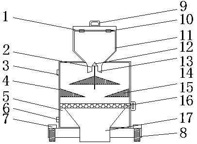
  • Feeding device for grain dryer
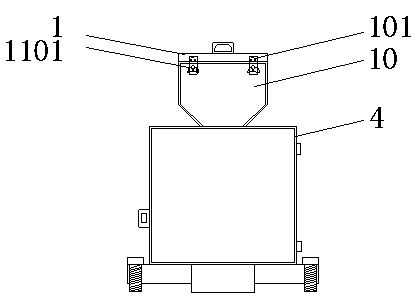
  • Feeding device for grain dryer
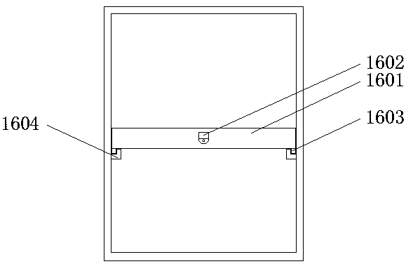
  • Feeding device for grain dryer

Examples


Embodiment Construction

[0017] The following will clearly and completely describe the technical solutions in the embodiments of the present invention with reference to the accompanying drawings in the embodiments of the present invention. Obviously, the described embodiments are only some, not all, embodiments of the present invention. Based on the embodiments of the present invention, all other embodiments obtained by persons of ordinary skill in the art without making creative efforts belong to the protection scope of the present invention.

[0018] In the description of the present invention, it should be noted that the terms "upper", "lower", "inner", "outer", "front end", "rear end", "both ends", "one end", "another end" The orientation or positional relationship indicated by etc. is based on the orientation or positional relationship shown in the drawings, and is only for the convenience of describing the present invention and simplifying the description, rather than indicating or implying that ...


PUM


Abstract

The invention discloses a feeding device for a grain dryer. The feeding device comprises a shell, a funnel and a mounting base. A first handle is fixedly installed at the top of a box cover by means of welding. A first feeding inlet is formed in one side of the bottom of the funnel. A second feeding inlet is formed in the bottom of the funnel and further located in one side of the first feeding inlet, and the first feeding inlet and the second feeding inlet stretch into the shell. First electric hot plates are fixedly installed on the two sides of a fixed baffle. Second electric hot plates arefixedly installed on the two sides of the inside of the shell. A screen cloth is fixedly installed inside the shell and further located below the second electric hot plates. Bevel angle stopping blocks are fixedly installed on the two sides of the bottom of the screen cloth. Bolts are fixedly installed on the two sides of the mounting base. A discharging outlet is fixedly formed in the bottom ofthe shell and further penetrates into the bottom of the mounting base. The feeding device for the grain dryer is convenient to dismantle and easy to operate, and feeding efficiency is improved.

Description

technical field [0001] The invention relates to the technical field of feeding devices, in particular to a feeding device for a grain dryer. Background technique [0002] With the development of the times, the continuous improvement of grain seed technology, the increase of per unit yield and the increase of the country's investment in grain drying equipment, more and more large, medium and small grain drying facilities are being built. Grain dryers are suitable for The equipment for drying grain, the grain dryer can kill insect eggs through high temperature treatment, completely solve the discoloration phenomenon in the drying process, and effectively solve the discoloration problem of grain drying. With the continuous development of the continuous development, users have also put forward higher requirements for the feeding device of the grain dryer. Most of the existing feeding devices are complicated to install and not easy to disassemble, and the functions are relatively...

Claims


Application Information

Patent Timeline
Patent Type & Authority Applications(China)
IPC IPC(8): F26B25/00F26B23/06A23B9/08
CPCA23B9/08F26B23/06F26B25/002F26B2200/06
Inventor 陆必发
Owner ANHUI SUNMIRO AGRI TECH
Learn More