Supercharge Your Innovation With Domain-Expert AI Agents!

Electronic delay-controlled detonator circuit and test method

A technology of delay control and switch control circuit is applied in the field of detonators, which can solve the problems of inability to realize automatic non-destructive testing, and achieve the effects of reducing labor and material costs, reducing circuit manufacturing costs, and simple operation process.

Pending Publication Date: 2018-12-18
江苏众芯邦软件科技有限公司
View PDF0 Cites 3 Cited by
  • Summary
  • Abstract
  • Description
  • Claims
  • Application Information

AI Technical Summary

Problems solved by technology

[0002] Due to the particularity of the working site of the electronic detonator and the complexity of the site, its stability must be guaranteed, which has high requirements for the stability and reliability of the electronic detonator device system, and it is often necessary to repeatedly test carefully before working on the blasting site. The existing non-destructive testing theory is not yet mature, and it is impossible to realize fully automatic non-destructive testing in the true sense. How to design the interface of non-destructive testing electronic detonators is particularly important
Traditional electronic detonators often use a single capacitor as a charging and discharging circuit, which has certain limitations

Method used

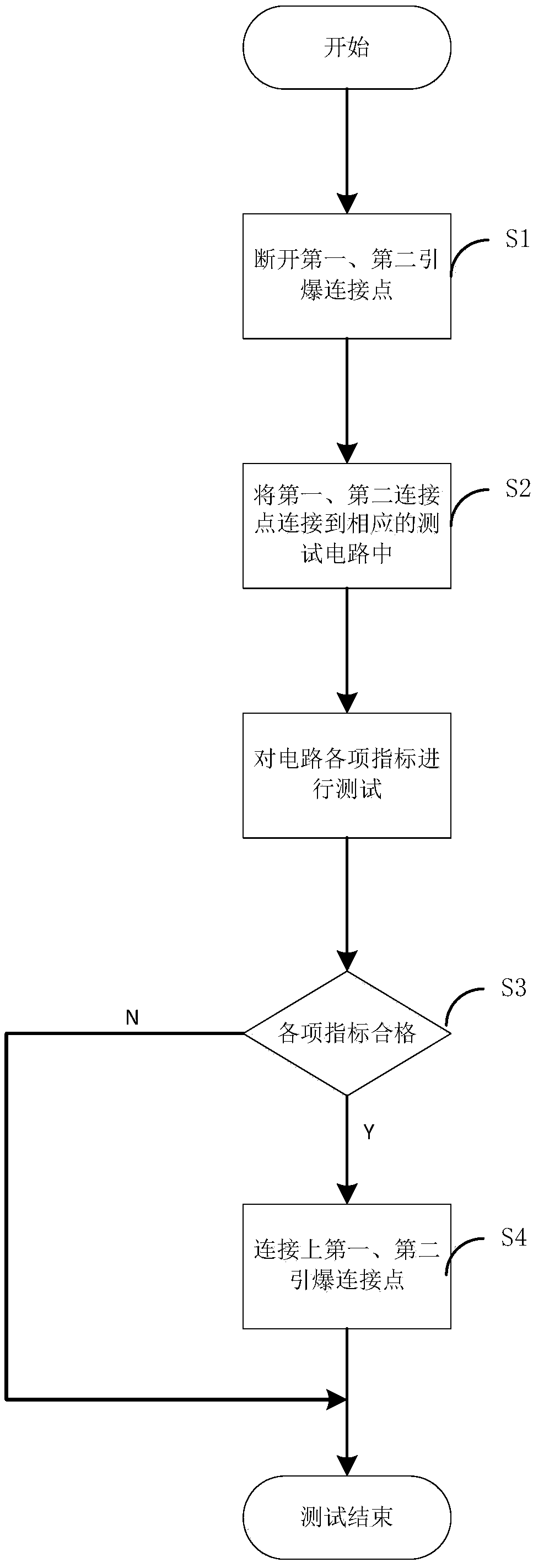

Image

  • Electronic delay-controlled detonator circuit and test method
  • Electronic delay-controlled detonator circuit and test method

Examples


Embodiment Construction

[0030] Embodiments of the present invention are described in detail below, examples of which are shown in the drawings, wherein the same or similar reference numerals designate the same or similar elements or elements having the same or similar functions throughout. The embodiments described below by referring to the figures are exemplary and are intended to explain the present invention and should not be construed as limiting the present invention.

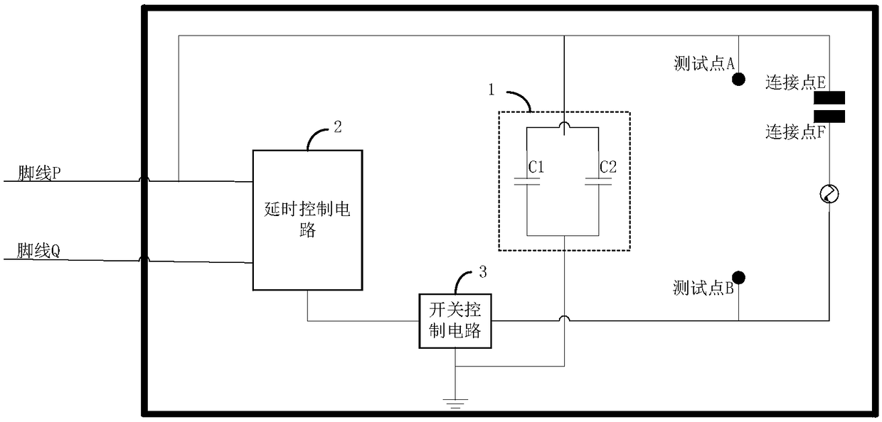
[0031] The invention provides a detonator circuit with electronic delay control, refer to the attached figure 1 As shown, it includes a detonator, a delay control circuit 2, a switch control circuit 3, a dual capacitor charging circuit 1, a first test point A, a second test point B, a first detonation connection point E, a second detonation connection point F, and a second detonation connection point F. Both the first detonation connection point E and the second detonation connection point F are the detonation connection points o...


PUM

PropertyMeasurementUnit
Diameteraaaaaaaaaa

Abstract

The invention provides an electronic delay-controlled detonator circuit and a test method. The electronic delay-controlled detonator circuit comprises a detonator, a delay control circuit, a switchingcontrol circuit, a double-capacitor charging circuit, a first test point, a second test point, a first detonating connection point and a second detonating connection point, wherein the first detonating connection point and the second detonating connection point are detonating connection points for the detonator, and the first test point and the second test point are test points for the detonator;the double-capacitor charging circuit comprises a first charging capacitor and a second charging capacitor, and the capacitance values of the first charging capacitor and the second charging capacitor are same; the positive pole of the first charging capacitor and the positive pole of the second charging capacitor are connected with each other and are both connected with the positive pole of a power source; and the negative pole of the first charging capacitor and the negative pole of the second charging capacitor are connected with each other and are both connected with the negative pole ofthe power source. The electronic delay-controlled detonator circuit increases the quantity of electric charge stored in the capacitors without increasing the complexity of a circuit design, thereby greatly reducing the circuit manufacturing cost.

Description

technical field [0001] The invention relates to the technical field of detonators, in particular to an electronic delay control detonator circuit and a testing method. Background technique [0002] Due to the particularity of the working site of the electronic detonator and the complexity of the site, its stability must be guaranteed, which has high requirements for the stability and reliability of the electronic detonator device system, and it is often necessary to repeatedly test carefully before working on the blasting site. The existing nondestructive testing theory is immature, and it is impossible to realize fully automatic nondestructive testing in the true sense. How to design the interface of the electronic detonator for nondestructive testing is particularly important. Traditional electronic detonators often use a single capacitor as a charging and discharging circuit, which has certain limitations. Contents of the invention [0003] The aim of the present inven...

Claims


Application Information

Patent Timeline
IPC IPC(8): F42C19/12F42C21/00
CPCF42C19/12F42C21/00
Inventor 杨国星朱传东
Owner 江苏众芯邦软件科技有限公司
Features
  • R&D
  • Intellectual Property
  • Life Sciences
  • Materials
  • Tech Scout
  • Unparalleled Data Quality
  • Higher Quality Content
  • 60% Fewer Hallucinations
Learn More