
High-power LED optical fiber coupling system

A fiber-optic coupling and high-power technology, applied in the field of high-power LED fiber-optic coupling systems, can solve the problems of being unable to adapt to manual control of lighting, large power supply and heat dissipation systems, etc., to achieve improved LED beam utilization, reasonable structure, and suitable for popularization and use. Effect

Pending Publication Date: 2018-12-18
苏州汇影光学技术有限公司
View PDF0 Cites 1 Cited by
  • Summary
  • Abstract
  • Description
  • Claims
  • Application Information

AI Technical Summary

Problems solved by technology

[0003] LED lighting is gradually expanding to the high-power field. In some special application scenarios, it is necessary to manually control the lighting area of ​​the beam. However, high-power light sources usually require a larger power supply and cooling system, which cannot meet the needs of manual control of lighting.

Method used


Image

  • High-power LED optical fiber coupling system

Examples


specific Embodiment 1

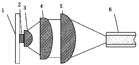
[0013] Specific embodiment one, please refer to figure 1 , a high-power LED optical fiber coupling system, comprising an LED cooling base plate 1, an LED chip 2, a first lens 3, a second lens 4, a third lens 5 and an optical fiber bundle 6, one side of the LED chip 2 is fixed on the LED On the heat dissipation base plate 1, the other side of the LED chip 2 is close to the incident surface of the first lens 3, and the outside of the first lens 3 is provided with a second lens 4, a third lens 5 and an optical fiber bundle 6 in sequence, The second lens 4 can form the beam converged by the first lens 3 into a parallel beam and emit it. The third lens 5 can focus the parallel beam emitted by the second lens. The incident end surface of the optical fiber bundle 6 is located at the third lens 5 The focal position of the third lens 5 at the focal position is smaller than the aperture of the optical fiber bundle 6, and the converging angle of the beam passing through the third lens 5 ...


PUM


Abstract

The invention relates to a high-power LED optical fiber coupling system, and belongs to the technical field of LED light sources. One side of an LED chip in the high-power LED optical fiber coupling system is fixed on an LED heat dissipation bottom plate, so that heat generated during the working of the LED chip can be rapidly transmitted to the LED heat dissipation bottom plate; the other side ofthe LED chip abuts against an incident surface of a first lens, most of optical fibers emitted by the LED chip can be converged by the first lens, so that an utilization rate of LED light beams is improved; the second lens is used for making light beams converged by the first lens become parallel light beams to be emitted out; the third lens is used for focusing the parallel light beams emitted by the second lens and transmitting light rays to the inside of an optical fiber bundle; and the high-power LED optical fiber coupling system is reasonable in structure, high in light utilization efficiency and suitable for popularization and application.

Description

technical field [0001] The invention relates to a high-power LED optical fiber coupling system, belonging to the technical field of LED light sources. Background technique [0002] With the continuous development of the industry, breakthroughs in technology, and vigorous promotion of applications, the luminous efficiency of LEDs is also constantly improving, and the price is constantly falling. The emergence of new combined tube cores has also continuously increased the power of a single LED tube (module). Through continuous efforts in research and development by peers, breakthroughs in new optical designs, and development of new lamp types, the situation of single products is expected to be further reversed. [0003] LED lighting is gradually expanding to the high-power field. In some special application scenarios, it is necessary to manually control the lighting area of ​​the beam. However, high-power light sources usually require a larger power supply and cooling system,...

Claims


Application Information

Patent Timeline
IPC IPC(8): G02B6/42G02B27/09
CPCG02B27/0955G02B6/4206G02B6/4272
Inventor 李治显
Owner 苏州汇影光学技术有限公司
Features
  • Generate Ideas
  • Intellectual Property
  • Life Sciences
  • Materials
  • Tech Scout
  • Unparalleled Data Quality
  • Higher Quality Content
  • 60% Fewer Hallucinations
Learn More