Device and method for testing RFID sensitivity

A technology for sensitivity and testing tooling, applied in the direction of testing sensing devices, electromagnetic radiation induction, instruments, etc., can solve the problems of high cost, no consideration of data, unsuitable for production line to build multiple test stations, etc., to achieve low cost and accuracy The effect of the test

Inactive Publication Date: 2018-12-18
天津科畅慧通信息技术有限公司
View PDF8 Cites 4 Cited by
  • Summary
  • Abstract
  • Description
  • Claims
  • Application Information

AI Technical Summary

Problems solved by technology

The transmission detects the sensitivity status online through the loopback, although it is convenient, it cannot really test the sensitivity
[0006] To sum up, the current method for RFID sensitivity testing in the existing technology uses a signal source to test the sensitivity of the reader, which is not only expensive, but also not suitable for the production line to build mult

Method used


Image

  • Device and method for testing RFID sensitivity
  • Device and method for testing RFID sensitivity
  • Device and method for testing RFID sensitivity

Examples


Embodiment 1

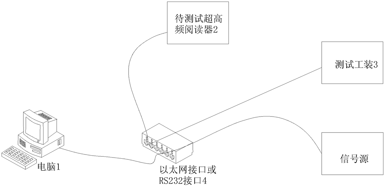
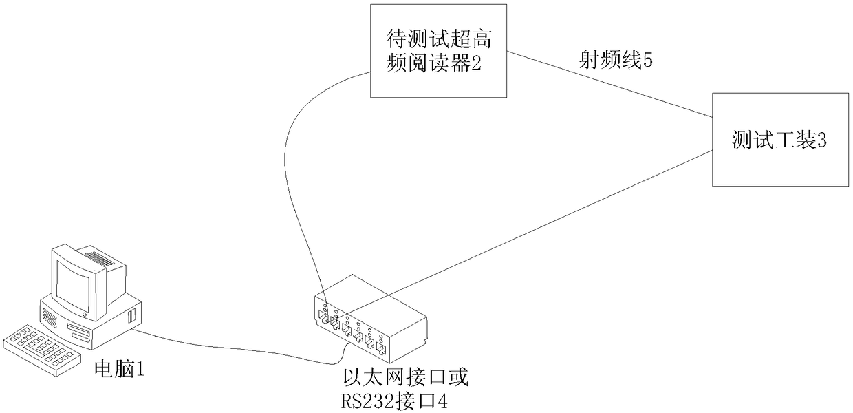
[0031] see Figure 2-3 , a device for testing RFID sensitivity, comprising a computer 1, a UHF reader to be tested 2 and a test tool 3; the computer 1, the UHF reader to be tested 2 and the test tool 3 communicate through an Ethernet interface or an RS232 interface 4 connect;

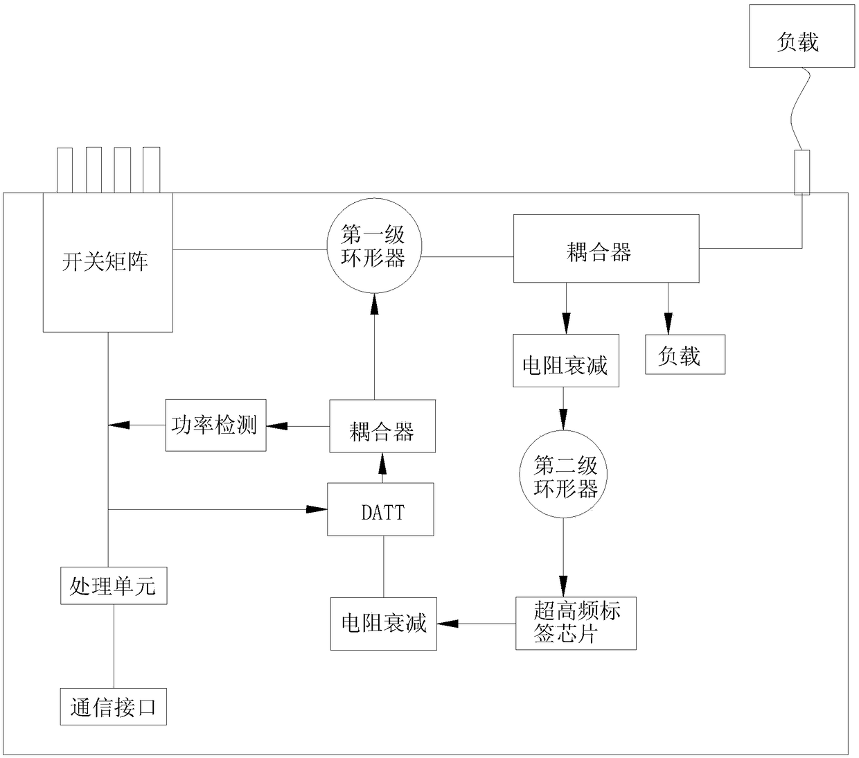
[0032] Among them, the computer 1 is used to start the sensitivity test, and counts the sensitivity under a specific bit error rate; the UHF reader 2 to be tested and the test tool 3 are connected by a radio frequency line 5, and the UHF reader to be tested 2 according to The UHF protocol sends inventory commands and carrier waves, and the UHF chip bound to the test fixture 3 replies with random numbers or EPC coded information or TID information according to the decoded command; the test fixture 3 can dynamically set the sensitivity threshold of the fixture board emission, Flexible configuration according to R&D or production line requirements, test fixture 3 is composed of switch matrix, first-stage ...

Embodiment 2

[0036] Based on the description of the above-mentioned embodiment 1, another embodiment provided by the present invention is: a method for testing RFID sensitivity, comprising the following steps:

[0037] Step 1: According to the UHF protocol, the UHF reader 2 to be tested first sends a single carrier in the sending window, which is used to activate the UHF passive chip on the test tool 3;

[0038] Step 2: The UHF reader 2 to be tested sends a forward inventory command. After the tag parses the forward command, it backscatters and modulates the carrier, and outputs the reverse data;

[0039] Step 3: Receive the information returned by the test tooling 3 at the receiving window of the UHF reader 2 to be tested. If the UHF reader 2 to be tested can successfully demodulate the EPC code or TID returned by the decoding tag, it is considered that this time The sensitivity test is passed, otherwise the test is considered to have failed.

[0040] Among them, according to the UHF pro...


PUM


Abstract

The invention discloses a device and a method for testing the RFID sensitivity, comprising a computer, a UHF reader to be tested and a test fixture. The computer, the UHF reader to be tested and the test fixture are communicatively connected through an Ethernet interface or an RS232 interface; the computer is used to start the sensitivity test, the reader sends the count command and single carrieraccording to the UHF protocol, and the UHF chip bound on the tooling board will reply the random number or EPC code information or TID information according to the decoded command. The tooling boardof the method consists of a ring, a coupler, a UHF tag chip, a numerically controlled attenuator, a power unit calibration unit and a microprocessor, etc. It can replace expensive testing instruments,and the testing results are more true and accurate.

Description

technical field [0001] The invention relates to the application technical field of research and development of UHF readers or production line testing sensitivity, in particular to a device and method for testing RFID sensitivity. Background technique [0002] UHF passive RFID systems generally consist of readers, antennas, and passive tags. It is necessary to test the receiving sensitivity of the reader in the process of R&D or production line production, so as to clarify the performance of the device, refer to figure 1 . [0003] Receiving sensitivity refers to the minimum signal level that the receiver needs to input at the input terminal of the receiver under the condition of satisfying a certain bit error rate. In the actual R&D or production process, the signal source is often used to simulate the electronic tag, and the reverse receiving sensitivity of the equipment is tested by adjusting the power and counting the bit error rate by the computer. In addition, the ca...

Claims


Application Information

Patent Timeline
IPC IPC(8): G06K7/00G06K7/10
CPCG06K7/0095G06K7/10009
Inventor 刘勇吴中平陈继光邓国勇吴纯杰刘朝阳
Owner 天津科畅慧通信息技术有限公司
Why Eureka
Try Eureka