Inertial power generation device, power generation system and control method

A power generation device and power generation system technology, applied in the direction of electromechanical devices, mechanical energy control, electrical components, etc., can solve the problems of low energy conversion efficiency, and achieve the effects of simple structure, improved conversion efficiency, and easy process

Inactive Publication Date: 2018-12-18
深圳美能动力科技有限公司
View PDF0 Cites 1 Cited by
  • Summary
  • Abstract
  • Description
  • Claims
  • Application Information

AI Technical Summary

Problems solved by technology

The use of permanent magnets has long been familiar to people, especially after the advent of NdFeB permanent magnet materials, the use of permanent magnet energy has been paid more and more attention by the industry, but the design of existing generators using permanent magnets is often limited. Designed inside the generator, although the design is ingenious, the energy conversion efficiency is still low

Method used


Image

  • Inertial power generation device, power generation system and control method
  • Inertial power generation device, power generation system and control method
  • Inertial power generation device, power generation system and control method

Examples


Embodiment 1

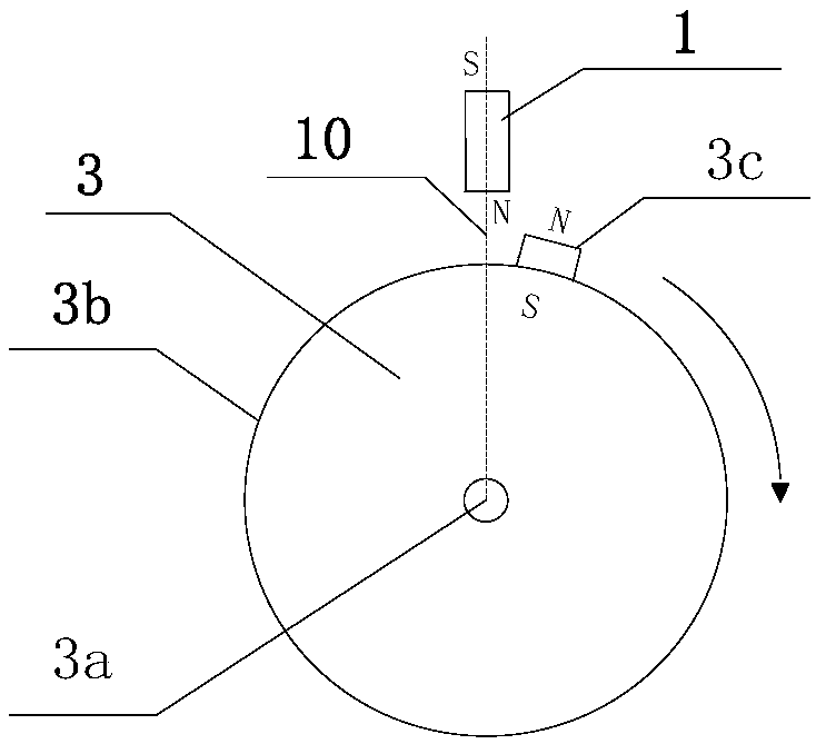
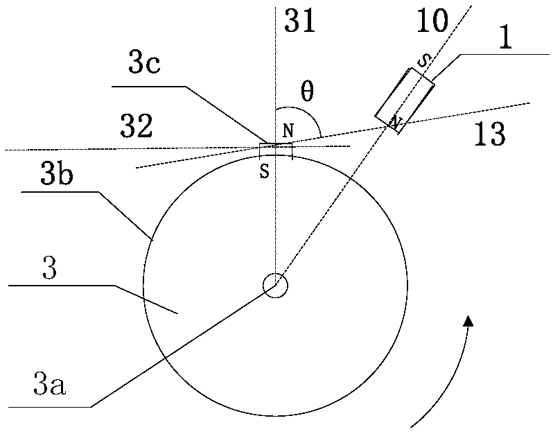
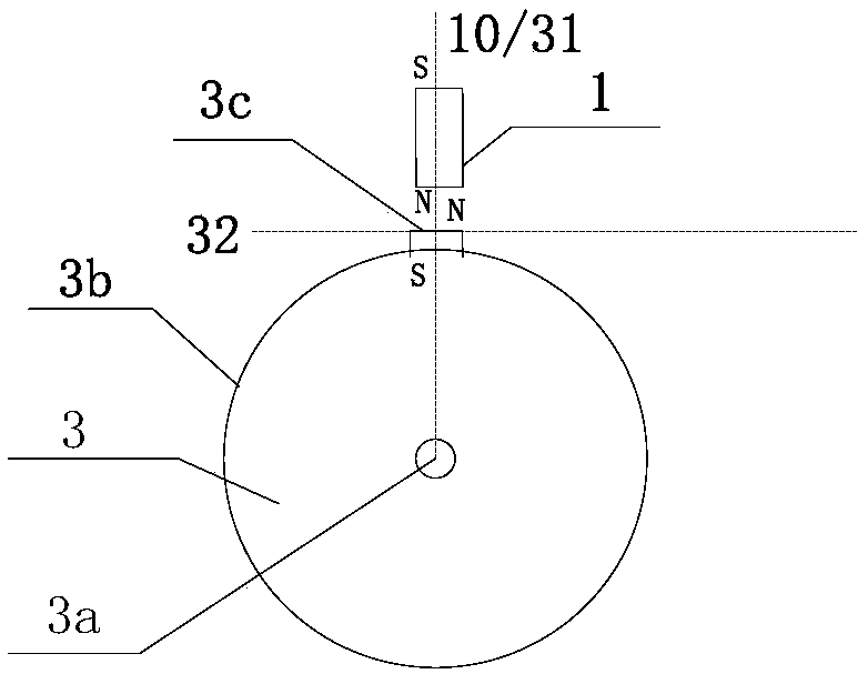
[0063] A kind of inertial power generating device of the present invention, comprises repulsive magnet 1, displacement device 2, inertial wheel 3 and generator 4; Generator 4 is conventional rotary generator; The center band hole of inertial wheel 3, this hole passes through The rotating shaft 4a of the generator 4 is mechanically connected with it to achieve the installation effect that the rotating shaft 3a axis of the inertia wheel 3 coincides with the rotating shaft 4a axis of the generator 4; the outer edge of the rim 3b of the inertia wheel 3 is provided with a rotating magnet 3c , the S pole faces the rotating shaft 3a, and the N pole faces the outer edge of the rim 3b, such as Figure 4 As shown; the displacement device 2 is composed of a reciprocating electric device, a set of 48V2000Ah lead-acid battery pack, motion sensor and power controller. The internal structure logic of the displacement device 2 is as follows: Figure 5 Shown; Wherein, motion sensor is a magnet...

Embodiment 2

[0067] All the magnetic poles of the repulsive magnet 1 and the rotating magnet 3c described in embodiment 1 are exchanged, that is, the N pole of the rotating magnet 3c arranged on the outer edge of the wheel 3b of the inertia wheel 3 faces the rotating shaft 3a, and the S pole faces the wheel rim 3b. Outer edge; Simultaneously, the bar-shaped repelling magnet 1 that is fixedly installed on the electric device changes to S pole and faces inertial wheel 3; Other parts are set and are identical with embodiment 1. The effect of this embodiment is similar to that of Embodiment 1.

Embodiment 3

[0069] On the basis of Embodiment 1, the rotating magnets 3c of the inertial wheel 3 are increased to 4, and the four rotating magnets surround the outer edge of the rim 3b of the inertial wheel 3 at equal intervals and are evenly distributed in the same polar direction, that is, around the inertial wheel 3 The outer edge of the rim 3b is provided with one at every 90 degree angle, and the four rotating magnets 3c have S poles facing the rotating shaft 3a, and N poles facing the outer edge of the rim 3b, as Figure 6 shown. The configuration of other parts of the inertial power generation device in this embodiment is the same as that described in Embodiment 1.

[0070] Every time the inertia wheel 3 of this embodiment rotates once, the motion sensor senses the position signal that the magnet 3c crosses the reference normal line 10 four times during the sequential rotation, and the logic of the power supply controller is changed accordingly: any one of the rotary magnets is in ...


PUM


Abstract

The invention discloses an inertial power generation device, a power generation system and a control method. The inertial power generation device comprises a repelling magnet, a displacement device, an inertial wheel and a generator. The repelling magnet is mechanically fixedly connected with the displacement device; At least one N/S pole facing the outer edge rotating magnet is arranged on the wheel rim of the inertial wheel, and the rotating shaft is coaxially arranged with the rotating shaft of the generator or is driven by a variable speed mechanical device; The inertia wheel and the displacement device are arranged adjacent to each other; The polarity of the repelling magnet facing the inertial wheel is the same as the polarity of the rotating magnet facing the outer edge. The displacement device comprises a battery, an action sensor, a power supply controller and an electric device. According to the relative position of the rotating magnet, the displacement device controls the repelling magnet to be located at the minimum distance from the inertial wheel or away from the inertial wheel, and increases the torque of the inertial wheel through the periodic magnetic repulsion, thereby driving the generator to generate electricity. The power generation system includes a discharge load and the inertial power generation device.

Description

technical field [0001] The invention relates to the design field of power generation devices and generator systems, in particular to an inertial power generation device based on magnetic torque, a power generation system and a control method. Background technique [0002] Generators are a conversion device of mechanical energy and electrical energy. They are widely used in industrial and agricultural production, national defense and daily life. Mechanical energy is generally generated by water turbines, steam turbines, diesel engines or other power machinery, and converted into electrical energy through generators. The working principle of the generator is based on the law of electromagnetic induction. The structure of conventional products is as follows: a magnetic induction circuit is formed by magnetic components, and electric energy is obtained in the coil winding circuit through the change of magnetic flux of the magnetic components, so as to achieve the conversion of me...

Claims


Application Information

Patent Timeline
Patent Type & Authority Applications(China)
IPC IPC(8): H02K7/02H02K7/00H02K7/18
CPCH02K7/00H02K7/02H02K7/1846Y02E60/16
Inventor 刘粤荣刘曦
Owner 深圳美能动力科技有限公司
Why Eureka
Try Eureka