
quantum key distribution time Bit-phase decoding method, device and system based on polarization orthogonal rotation

A technology of quantum key distribution and polarization orthogonality, applied to key distribution, can solve problems such as increasing system complexity and cost, increasing bit error rate, and unstable phase decoding interference

Active Publication Date: 2018-12-18
CHINA ACADEMY OF ELECTRONICS & INFORMATION TECH OF CETC
View PDF10 Cites 2 Cited by
  • Summary
  • Abstract
  • Description
  • Claims
  • Application Information

AI Technical Summary

Problems solved by technology

The time-base decoding in time-phase coding is not affected by the change of polarization state. However, when the phase base is interferometrically decoded, due to the birefringence of the transmission fiber and the codec interferometer fiber, there is a problem of polarization-induced fading, which leads to unstable decoding interference. The bit error rate increases. If the deviation correction equipment is added, the complexity and cost of the system will be increased, and it will be difficult to apply stably to strong interference situations such as overhead optical cables and road and bridge optical cables.
For the quantum key distribution time-phase encoding scheme, how to solve the phase decoding interference instability caused by polarization-induced fading in the application of time bit-phase encoding quantum key distribution in order to achieve stable and efficient phase interference decoding is Hotspots and difficulties in the application of quantum secure communication based on existing optical cable infrastructure

Method used


Image

  • quantum key distribution time Bit-phase decoding method, device and system based on polarization orthogonal rotation
  • quantum key distribution time Bit-phase decoding method, device and system based on polarization orthogonal rotation
  • quantum key distribution time Bit-phase decoding method, device and system based on polarization orthogonal rotation

Examples


Embodiment Construction

[0063] Preferred embodiments of the present invention will be specifically described below in conjunction with the accompanying drawings, wherein the accompanying drawings constitute a part of the application and are used together with the embodiments of the present invention to explain the principle of the present invention. For the sake of clarity and simplicity, detailed descriptions of known functions and structures of the devices described herein will be omitted when it may obscure the subject matter of the present invention.

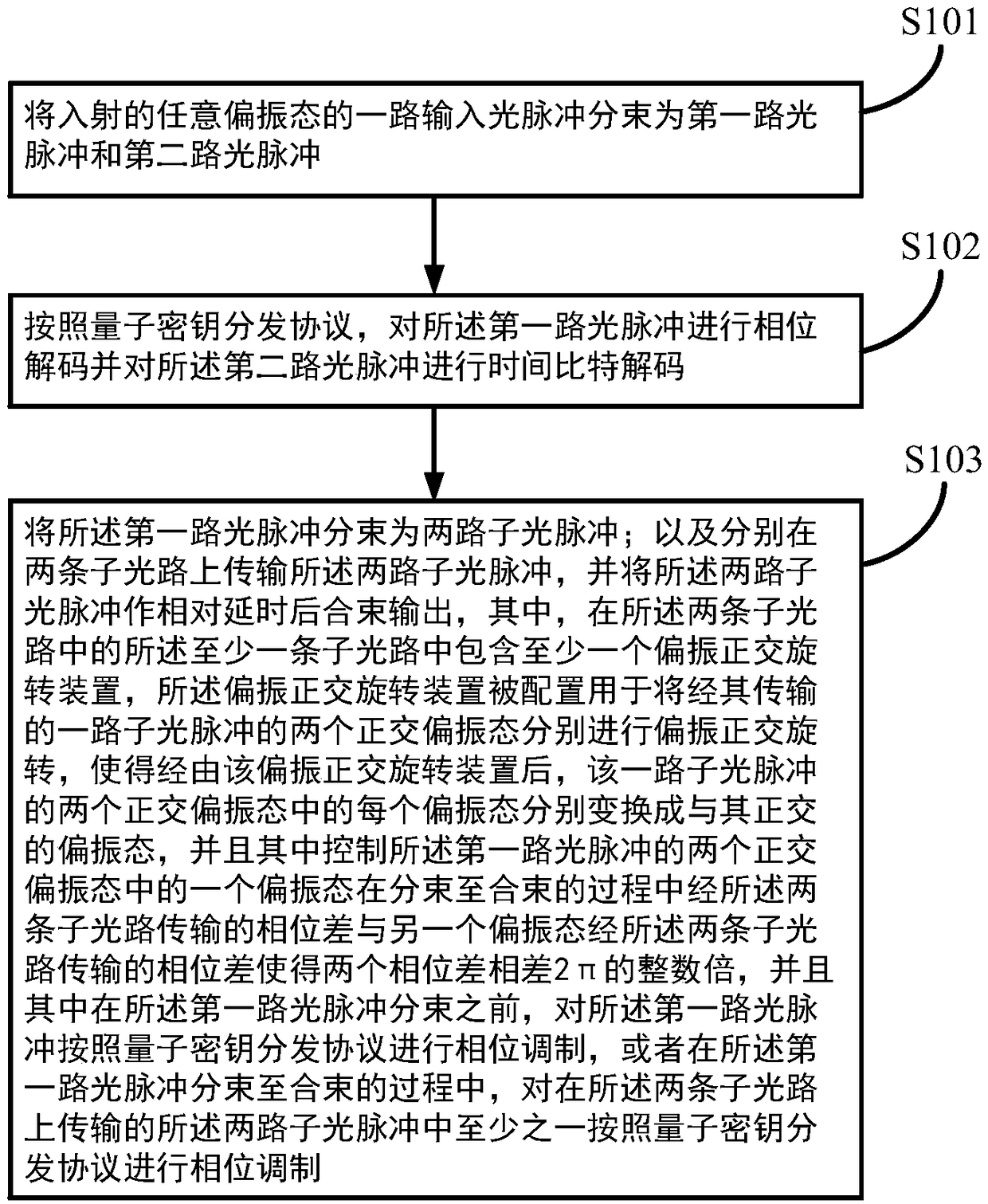
[0064] A kind of quantum key distribution time bit-phase decoding method based on polarization orthogonal rotation of a preferred embodiment of the present invention is as follows: figure 1 As shown, it specifically includes the following steps:

[0065] Step S101 : splitting an incoming light pulse of any polarization state into a first light pulse and a second light pulse.

[0066] Specifically, the incident input light pulse is of any polarizat...


PUM


Abstract

A Quantum Key Distribution Time Bit-Phase decoding method and apparatus and corresponding system Based on Polarization Orthogonal Rotation. The method comprises the following steps of: splitting an input optical pulse into a first optical pulse and a second optical pulse; performing phase decoding on The first optical pulse, and performing time bit decoding on the second optical pulse. Phase decoding of the first optical pulse includes splitting the first optical pulse into two sub-optical pulses transmitted on two sub-optical paths, At that same time, At least one sub-optical path comprisingat least one polarization orthogonal rotating mean, controlling The two orthogonal polarization states of the first optical pulse to differ from each other by an integer multiple of the phase difference 2Pi between the two sub-optical paths in the process of beam splitting to beam combining, and performing phase modulation on the first optical pulse before beam splitting or performing phase modulation on one of the two sub-optical pulses in the process of beam splitting to beam combining. The invention can realize the time bit Phase-coded quantum key distribution scheme for achieving environmental interference immunity..

Description

technical field [0001] The present invention relates to the technical field of optical transmission secure communication, in particular to a quantum key distribution time bit-phase decoding method and device based on polarization orthogonal rotation, and a quantum key distribution system including the device. Background technique [0002] Quantum secure communication technology is a frontier hot field combining quantum physics and information science. Based on the quantum key distribution technology and the principle of one-time pad cryptography, quantum secure communication can realize the secure transmission of information in open channels. Quantum key distribution is based on physical principles such as the Heisenberg uncertainty relation of quantum mechanics and the quantum non-cloning theorem. It can safely share keys between users and detect potential eavesdropping behaviors. It can be applied to national defense, government affairs, and finance. , electric power and ...

Claims


Application Information

Patent Timeline
Patent Type & Authority Applications(China)
IPC IPC(8): H04L9/08H04B10/70H04B10/524H04B10/532H04B10/556
CPCH04B10/70H04L9/0858H04B10/524H04B10/532H04B10/5561Y02D30/70
Inventor 许华醒
Owner CHINA ACADEMY OF ELECTRONICS & INFORMATION TECH OF CETC
Learn More