Filament calibration method, device and electronic device

A calibration method and calibration device technology, applied in X-ray equipment, electrical components, etc., can solve the problem of low tube current accuracy, achieve the effects of improved accuracy, accurate filament emission curve, and improved service life

Active Publication Date: 2018-12-18
SUZHOU POWERSITE ELECTRIC CO LTD
View PDF5 Cites 5 Cited by
  • Summary
  • Abstract
  • Description
  • Claims
  • Application Information

AI Technical Summary

Problems solved by technology

[0006] In view of this, the embodiments of the present invention provide a filament calibration method, device and elect

Method used


Image

  • Filament calibration method, device and electronic device
  • Filament calibration method, device and electronic device
  • Filament calibration method, device and electronic device

Examples


Embodiment Construction

[0054]In order to make the purposes, technical solutions and advantages of the embodiments of the present invention clearer, the technical solutions in the embodiments of the present invention will be clearly and completely described below with reference to the accompanying drawings in the embodiments of the present invention. Obviously, the described embodiments These are some embodiments of the present invention, but not all embodiments. Based on the embodiments of the present invention, all other embodiments obtained by those skilled in the art without creative efforts shall fall within the protection scope of the present invention.

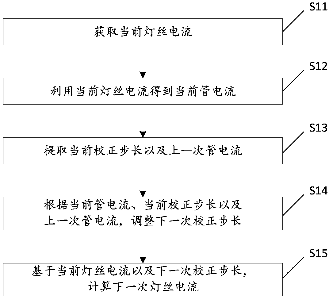
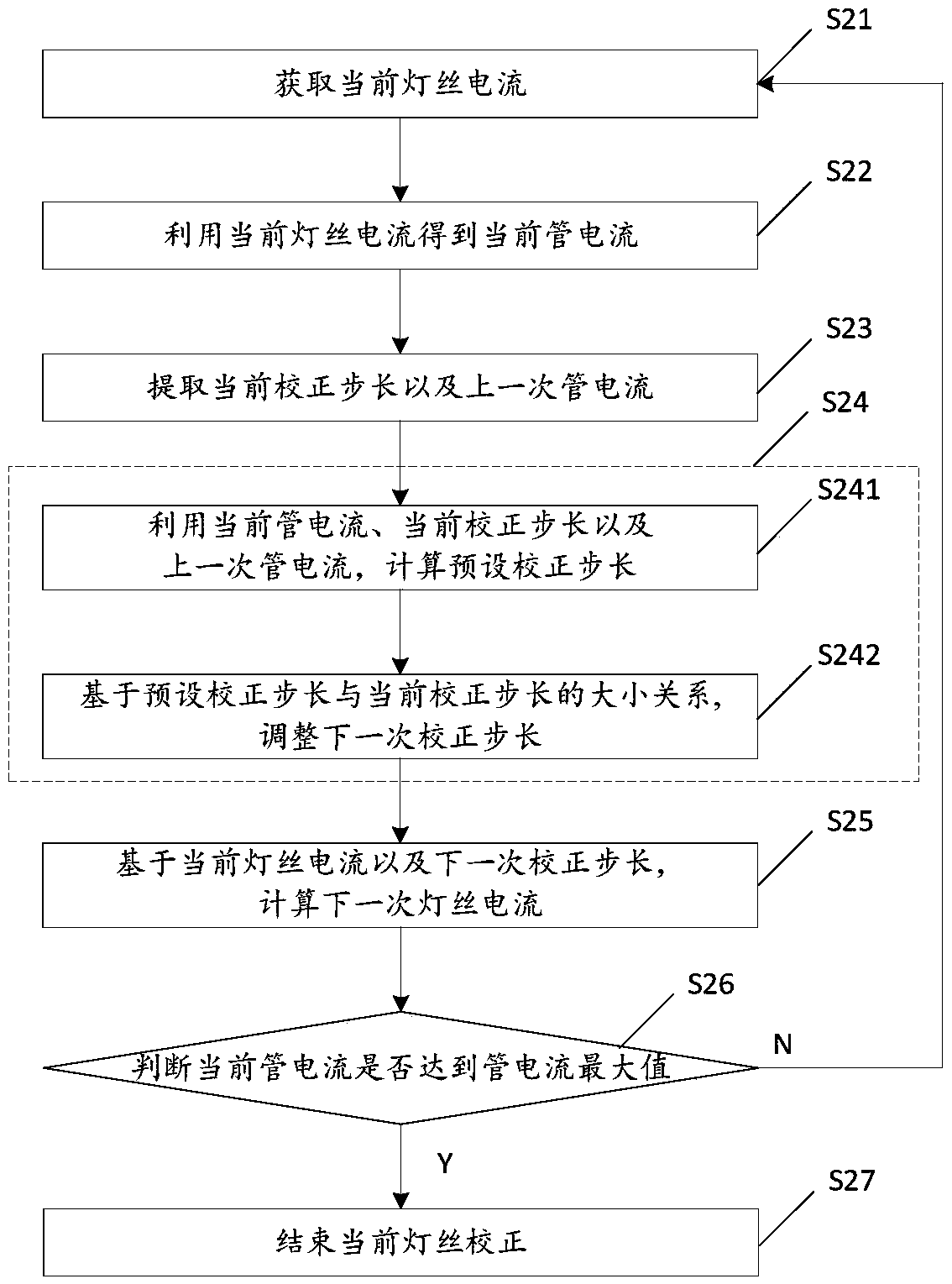
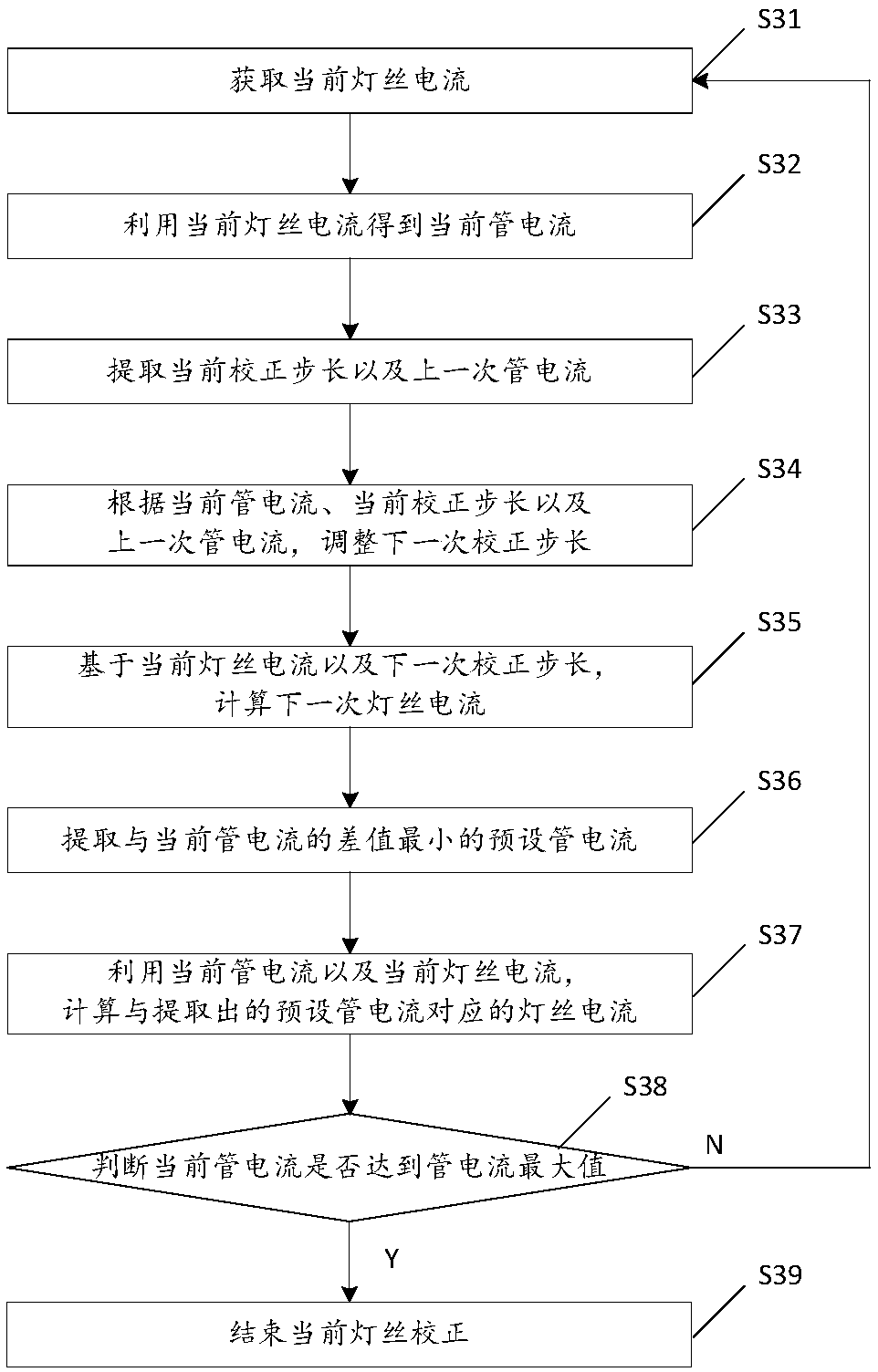
[0055] It should be noted that the filament calibration method provided by the embodiment of the present invention is a filament calibration under a tube voltage. Specifically, through the filament current exposure, the tube current is collected, and then the method of changing the correction step is used to calculate the filament current for ...


PUM


Abstract

The invention discloses a filament correction method, a device and an electronic device, wherein, the method comprises the steps of obtaining a current filament current; Obtaining the current tube current by using the current filament current; Extracting the current correction step size and the last tube current; Adjusting the next correction step length according to the current tube current, thecurrent correction step length and the last tube current; Calculating a next filament current based on the current filament current and the next correction step. The next calibration step is adjustedaccording to the change of the current. When the change of the current is larger and larger, the calibration step is automatically reduced, and the precision of the current is improved. In addition, the accuracy of the tube current can be ensured with the least number of exposure times by the filament correction method with variable step size, and the service life of the ray tube can be prolonged.

Description

technical field [0001] The present invention relates to the technical field of ray generating devices, in particular to a filament calibration method, device and electronic equipment. Background technique [0002] A radiation generating device is a commonly used medical device, which is used to form a photographic image by irradiating radiation to the party to be detected and receiving the radiation that penetrates the party to be detected. In a radiation generating device, radiation is generated and emitted from a radiation tube. [0003] Specifically, the ray tube is a high-vacuum cathode ray diode, which has an anode and a cathode, and a filament is arranged on the cathode. During the operation of the ray tube, by applying current to the cathode filament, the filament is heated and free electrons are generated, and then a high voltage is applied to the cathode and anode. Due to the sharp increase in the potential difference between the cathode and the anode, driven by a...

Claims


Application Information

Patent Timeline
IPC IPC(8): H05G1/26H05G1/34
CPCH05G1/265H05G1/34
Inventor 郝建伟陈飞王彦为范声芳王万全
Owner SUZHOU POWERSITE ELECTRIC CO LTD
Why Eureka
Try Eureka