Metal processing mold having automatic feeding and discharging functions

An automatic loading and unloading, metal processing technology, applied in metal processing, metal processing equipment, forming tools, etc., can solve the problems of inability to ensure the safety of staff loading and unloading, unable to adjust the mold, increase working time, etc., to increase the labor force. , the effect of increasing the experimental cost and speeding up the production efficiency

Inactive Publication Date: 2018-12-21
宁国市挚友合金钢材料有限公司
View PDF8 Cites 1 Cited by
  • Summary
  • Abstract
  • Description
  • Claims
  • Application Information

AI Technical Summary

Problems solved by technology

[0003] In the prior art, the molds are all fixed devices. Once they are positioned, the molds cannot be adjusted. Sometimes the inaccurate positioning of the molds will cause large stamping errors, punching deviations, etc., which will affect product quality, prolong delivery dates, and reduce corporate profits. Due to the need for manual loading and unloading during processing, a lot of manpower is wasted, the working time is increased, and the safety of staff loading and unloading cannot be guaranteed, so a metal processing mold with automatic loading and unloading functions is needed to solve the above problems

Method used


Image

  • Metal processing mold having automatic feeding and discharging functions
  • Metal processing mold having automatic feeding and discharging functions
  • Metal processing mold having automatic feeding and discharging functions

Examples


Embodiment Construction

[0020] In order to make the technical means, creative features, goals and effects achieved by the present invention easy to understand, the present invention will be further described below in conjunction with specific embodiments.

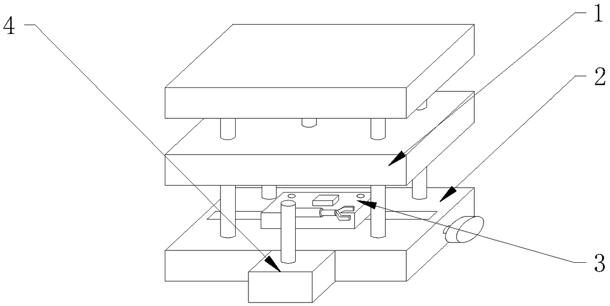
[0021] see Figure 1-Figure 3 , the present invention provides a technical solution: a metal processing mold with automatic loading and unloading functions, including a mold main body 1, a lower die 2, an adjustment mechanism 3 and a loading and unloading mechanism 4, and the lower die 2 is arranged at the lower end of the mold main body 1 , the adjustment mechanism 3 is installed on the upper end surface of the lower die 2, the mold main body 1 is arranged above the adjustment mechanism 3, and the loading and unloading mechanism 4 is fixed on the front end of the lower die 2.

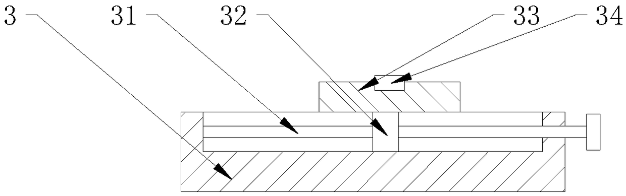
[0022] The adjustment mechanism 3 includes a screw rod 31, a bearing seat 32, a punch 33 and a workpiece splint 34. The screw rod 31 is arranged inside the lower die 2, th...


PUM


Abstract

The invention provides a metal processing mold having automatic feeding and discharging functions. The metal processing mold comprises a lower pressing die, a screw rod, a bearing seat, a male die, awork clamping board, a servo motor, a rotating shaft, an electric telescopic rod and an electromagnet, wherein the screw rod is arranged in the lower pressing die; the bearing seat is mounted on the screw rod; the male die is fixed to the upper end surface of the bearing seat, and is arranged on the upper end surface of the lower pressing die; the work clamping board is assembled on the upper endsurface of the male die, and through the design, a fine adjustment function is realized; the servo motor is fixed to the front end of the lower pressing die; the rotating shaft is mounted at the upperend of the servo motor; the electric telescopic rod is fixed at the right end of the rotating shaft; the electromagnet is mounted at the right end of the electric telescopic rod; and the electric telescopic rod and the electromagnet are arranged above the lower pressing die, and through the design, automatic feeding and automatic discharging can be performed. According to the metal processing mold disclosed by the invention, the fine adjustment function is realized, the automatic feeding and discharging functions are realized, and the metal processing mold is high in practicality, good in safety and high in reliability.

Description

technical field [0001] The invention relates to a metal processing mold with automatic loading and unloading functions, which belongs to the technical field of molds. Background technique [0002] Molds, various molds and tools used in industrial production for injection molding, blow molding, extrusion, die-casting or forging forming, smelting, stamping, etc. to obtain the required products, in short, molds are tools used to make shaped objects , this tool is composed of various parts, and different molds are composed of different parts. It mainly realizes the processing of the shape of the article through the change of the physical state of the formed material. [0003] In the prior art, the molds are all fixed devices. Once they are positioned, the molds cannot be adjusted. Sometimes the inaccurate positioning of the molds will cause large stamping errors, punching deviations, etc., which will affect product quality, prolong delivery dates, and reduce corporate profits. ...

Claims


Application Information

Patent Timeline
Patent Type & Authority Applications(China)
IPC IPC(8): B21D37/10B21D43/18B21D45/06B21C51/00
CPCB21D37/10B21C51/00B21D43/18B21D45/06
Inventor 王青云
Owner 宁国市挚友合金钢材料有限公司
Why Eureka
Try Eureka