A low-pressure casting mold for a vehicle box
A low-pressure casting and box body technology, applied in the field of aluminum alloy casting, can solve the problems of under-casting or unclear outline, local pores in castings, uneven exhaust, etc., to achieve reasonable and ingenious structural design, full tapping threads, Good exhaust effect
- Summary
- Abstract
- Description
- Claims
- Application Information
AI Technical Summary
Problems solved by technology
Method used
Image
Examples
Embodiment 1
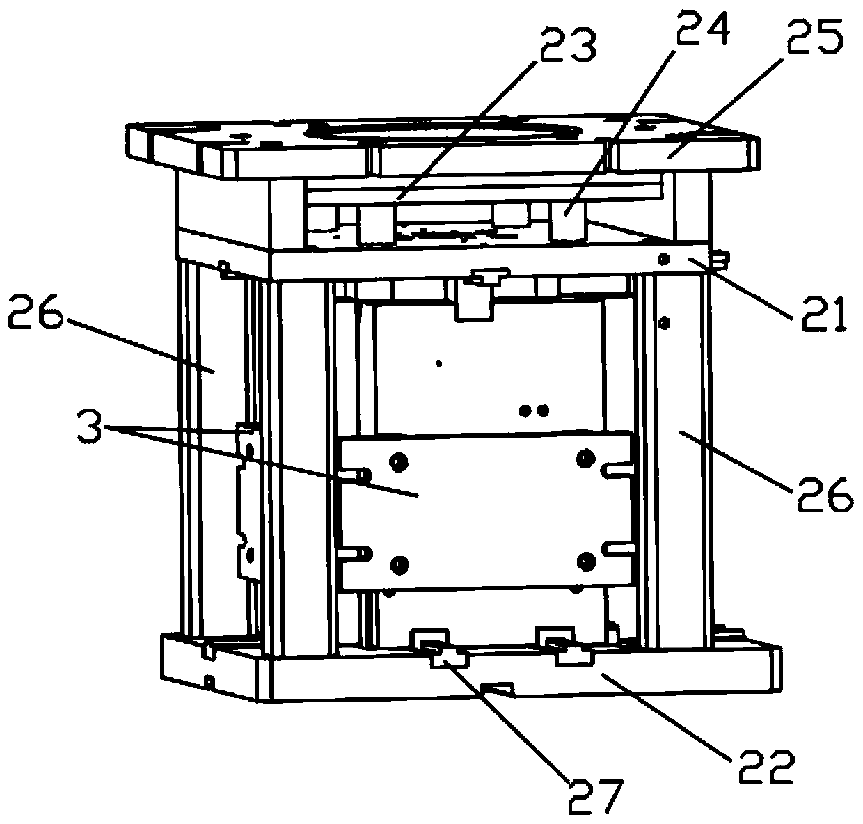
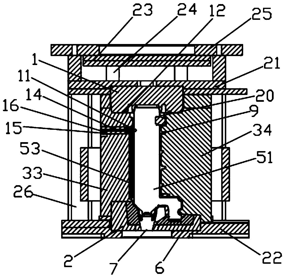
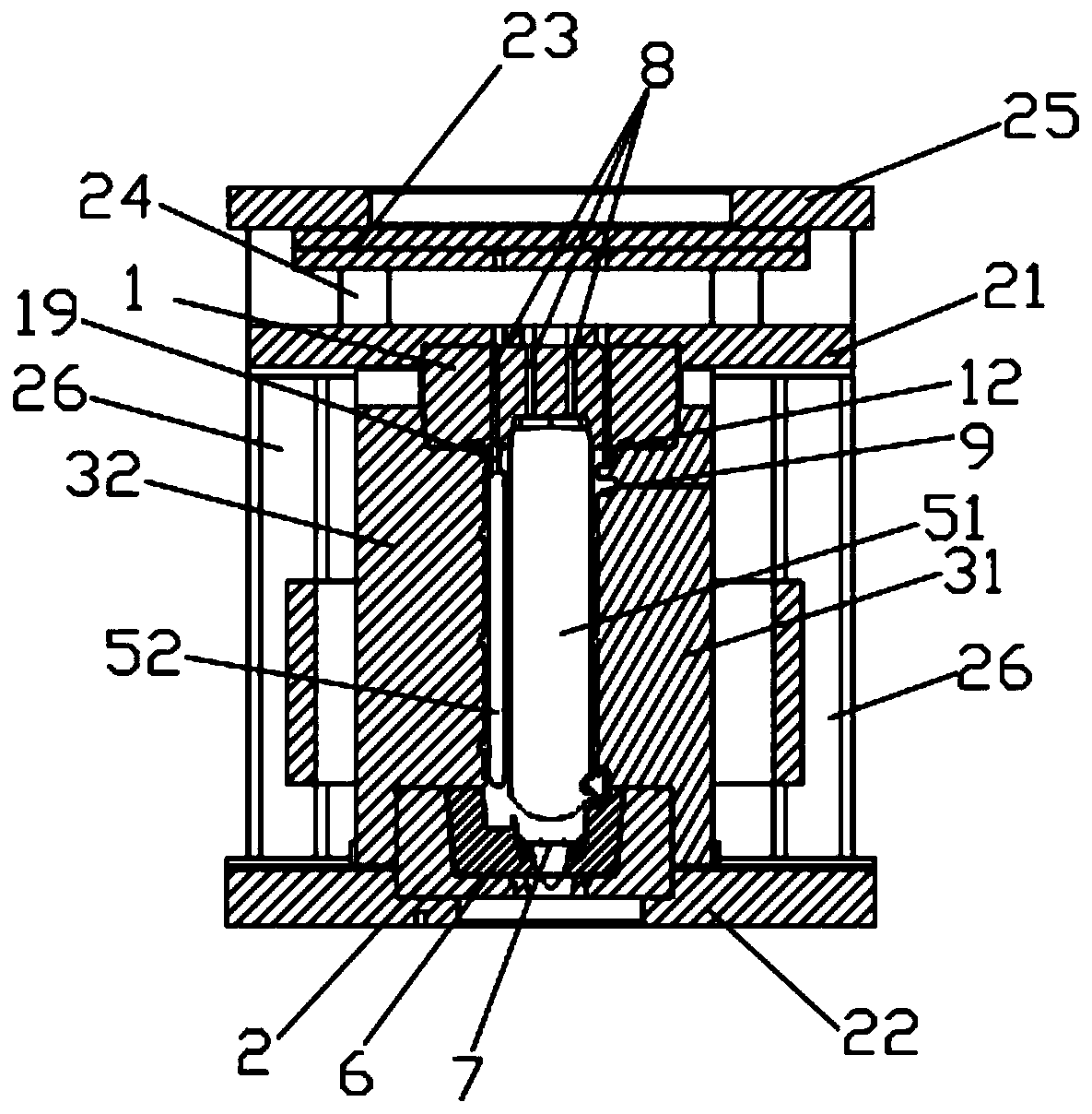
[0043] Please refer to figure 1 , figure 2 , image 3 and Figure 4 As shown, this embodiment provides a low-pressure casting mold for a vehicle box body, including an upper mold 1, a lower mold 2, and a side mold assembly 3 arranged between the upper mold 1 and the lower mold 2, specifically, the upper mold 1 Fixed on the upper mold fixed plate 21, the lower mold 2 is fixed on the upper mold fixed plate 22, and between the upper mold fixed plate 21 and the upper mold fixed plate 22 is provided with a fixed upper mold fixed plate 21 and an upper mold fixed plate 22 Four support columns 26, four support columns 26 are distributed in the four right angles where the upper mold fixed plate 21 is opposite to the upper mold fixed plate 22. The slide rail 27 that is slidably connected with the side mold assembly 3 is installed on the lower fixed plate, and the side mold assembly 3 includes a front side mold 31, a rear side mold 32, a left side mold 33 and a right side mold 34. S...
Embodiment 2
[0056] Please combine figure 2 and 12 As shown, this embodiment has been further improved on the basis of Embodiment 1. On the left side mold 33, there are inlaid holes 15 communicating with the casting cavity 9 and inserts 16 that match the inlaid holes 15, and the plugs 14 is inserted into the casting cavity 9 along the middle part of the insert 16, and on the mating surface of the side mold assembly 3 embedding hole 15 and the insert 16, there are at least two pull-throughs along the casting cavity 9 to the outside of the side mold assembly 3. The variable diameter channel 17 is provided with a recessed groove along the side mold at the place where the insert 16 is embedded along the casting cavity 9, and here it is at the upper end of the metal casting cavity 9, which can be connected with the side mold shell The disassembled and connected insert 16 design can effectively utilize the variable diameter channel 17 to discharge the gas in the inner nest groove of the castin...
Embodiment 3
[0059] Please combine Figure 5 and Figure 8 As shown, this embodiment has been further improved on the basis of Embodiment 2. Specifically, a plurality of exhaust sink holes 18 can be set on the mating surface of the water channel positioning core head and the main sand core 51; this embodiment provides two One exhaust sink hole 18 is an example, and two exhaust sink holes 18 are mirror-symmetrically arranged along the center of the bottom surface of the boss structure. Since the water channel sand core 52 is placed vertically in the vehicle exhaust gas treatment box mold, they are mirror-symmetrically arranged side by side. The exhaust sink hole 18 can introduce the gas into the main sand core 51 along the direction of gas spreading, which has a better exhaust effect, and the structural design is simple and ingenious.
[0060] In addition, in this embodiment, the diameter of the two circular exhaust sink holes 18 is 12 mm, which can effectively increase the exhaust area of...
PUM
 Abstract
Description
Claims
Application Information
 - R&D
- Intellectual Property
- Life Sciences
- Materials
- Tech Scout
- Unparalleled Data Quality
- Higher Quality Content
- 60% Fewer Hallucinations
Browse by: Latest US Patents, China's latest patents, Technical Efficacy Thesaurus, Application Domain, Technology Topic, Popular Technical Reports.
© 2025 PatSnap. All rights reserved.Legal|Privacy policy|Modern Slavery Act Transparency Statement|Sitemap|About US| Contact US: help@patsnap.com


