
Machining production device for medical treatment facilities

A production device and facility technology, applied in the field of medical facility processing and production devices, can solve problems affecting the quality and speed of medical bed preparation, increase labor and economic costs, and increase occupational diseases of staff, so as to increase the stability of use and improve work efficiency. Efficiency, the effect of increasing the service life

Inactive Publication Date: 2018-12-21
广州爵诺医疗器械有限公司
View PDF0 Cites 2 Cited by
  • Summary
  • Abstract
  • Description
  • Claims
  • Application Information

AI Technical Summary

Problems solved by technology

[0002] During the preparation of multi-functional medical beds, especially when the medical bed is perforated, a large amount of dust will be generated. Inhaling the dust into the body will increase the occupational diseases of the staff and increase labor and economic costs. The traditional medical bed drilling mainly relies on the workers to hold the punching machine to perform manual drilling, which is greatly conducive to convenient and quick drilling. operation, but the existing problem is that in the process of manual drilling, because the drill bit is aligned with the medical bed body only by manual experience, people's hands are prone to shaking when drilling, which will easily make the hole Skewing, which greatly affects the quality and speed of medical bed preparation

Method used


Image

  • Machining production device for medical treatment facilities
  • Machining production device for medical treatment facilities
  • Machining production device for medical treatment facilities

Examples


Embodiment Construction

[0012] Combine below Figure 1-3 The present invention will be described in detail.

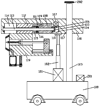
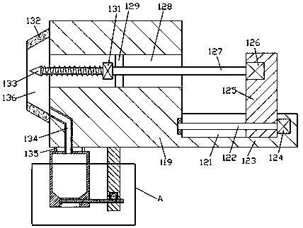
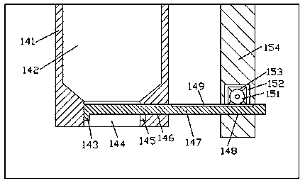
[0013] refer to Figure 1-3 , a medical facility processing and production device according to an embodiment of the present invention, comprising a walking frame 100, a vertical arm 103 is fixed at the top of the walking frame 100, and a first sliding cavity is provided up and down inside the vertical arm 103 117, the first sliding chamber 117 is slidably installed with a lifting frame 118, and the bottom end surface of the lifting frame 118 is provided with a second sliding chamber 114, and the first dovetails are respectively slidingly fitted in the second sliding chamber 114. block 112 and the second dovetail block 108, the second dovetail block 108 is internally threaded and installed with a first screw rod 113, the first screw rod 113 is clearance fit with the first dovetail block 112, and the The left extension end of the first screw-shaped rod 113 is rotationally connected with the l...


PUM


Abstract

The invention discloses a machining production device for medical treatment facilities. The machining production device comprises a traveling vehicle frame, wherein the top end of the traveling vehicle frame is fixedly provided with a vertical arm; a first sliding cavity is formed in the vertical arm in an up-down penetrating manner; a rising and falling rack is mounted in the first sliding cavityin a sliding fit manner; a second sliding cavity is formed in the bottom end surface of the rising and falling rack; a first dovetail block and a second dovetail block are respectively mounted in thesecond sliding cavity in a sliding fit manner; a first spiral rod is mounted in the second dovetail block in a threaded fit manner and is in clearance fit with the first dovetail block; the extensiontail end of the left side of the first spiral rod is connected with the inner wall of the left side of the second sliding cavity in a rotating fit manner; depressed cavities are symmetrically formedin the left-sided end surface of the second dovetail block upwards and downwards; buffer elastic plates are fixedly mounted between the inner side walls of the depressed cavities and the right-sided end surface of the first dovetail block; a third sliding cavity is formed in the left-sided end surface of the second dovetail block and positioned on the upper sides of the depressed cavities; and a guiding block is mounted in the third sliding cavity in a sliding fit manner.

Description

technical field [0001] The invention relates to the technical field of medical bed processing, in particular to a processing and production device for medical facilities. Background technique [0002] During the preparation of multi-functional medical beds, especially when the medical bed is perforated, a large amount of dust will be generated. Inhaling the dust into the body will increase the occupational diseases of the staff and increase labor and economic costs. The traditional medical bed drilling mainly relies on the workers to hold the punching machine to perform manual drilling, which is greatly conducive to convenient and quick drilling. operation, but the existing problem is that in the process of manual drilling, because the drill bit is aligned with the medical bed body only by manual experience, people's hands are prone to shaking when drilling, which will easily make the hole If it is crooked, it will greatly affect the quality and speed of the preparation of ...

Claims


Application Information

Patent Timeline
Patent Type & Authority Applications(China)
IPC IPC(8): B23B39/14B23B41/00B23B47/30B23Q11/00
CPCB23B39/14B23B41/00B23B47/30B23Q11/0042
Inventor 覃日雄
Owner 广州爵诺医疗器械有限公司
Learn More