
Aluminum plastic plate automatic machining robot

An automatic processing and robotic technology, applied in metal processing machinery parts, metal processing equipment, manufacturing tools, etc., can solve problems such as affecting the work process, high work efficiency, affecting tool life, etc., to reduce labor intensity and improve work efficiency. , the effect of prolonging tool life

Active Publication Date: 2018-12-21
任丘市华泰铝业有限公司
View PDF7 Cites 2 Cited by
  • Summary
  • Abstract
  • Description
  • Claims
  • Application Information

AI Technical Summary

Problems solved by technology

[0003] In order to solve the above problems, the present invention provides an automatic processing robot for aluminum-plastic panels, which can solve the need for manual slotting in the existing aluminum-plastic panel slotting process. When starting slotting, the slotting knife directly opens the aluminum-plastic panel. Grooves are easy to affect tool life. Some grooves are not fully formed during manual grooving, and scraps will accumulate on both sides of the groove during grooving, which affects the working process. Manual grooving is easy to deviate from the original position. The chips are not cleaned up in time, it takes a long time, the labor intensity is high, and the efficiency is low. It can realize the function of automatically grooving the aluminum-plastic panel and collecting the chips. To achieve the effect of cushioning, the tool life is extended, and a reciprocating groove is carried out until it is completely formed. During the groove process, the chips accumulated on both sides are automatically cleared away, and the automatic positioning avoids deviation from the position during groove, and the generated chips are timely. Cleaning takes a short time, and has the advantages of simple operation, low labor intensity and high work efficiency

Method used


Image

  • Aluminum plastic plate automatic machining robot
  • Aluminum plastic plate automatic machining robot
  • Aluminum plastic plate automatic machining robot

Examples


Embodiment Construction

[0029] In order to make the technical means, creative features, goals and effects achieved by the present invention easy to understand, the present invention will be further described below in conjunction with specific illustrations. It should be noted that, in the case of no conflict, the embodiments in the present application and the features in the embodiments can be combined with each other.

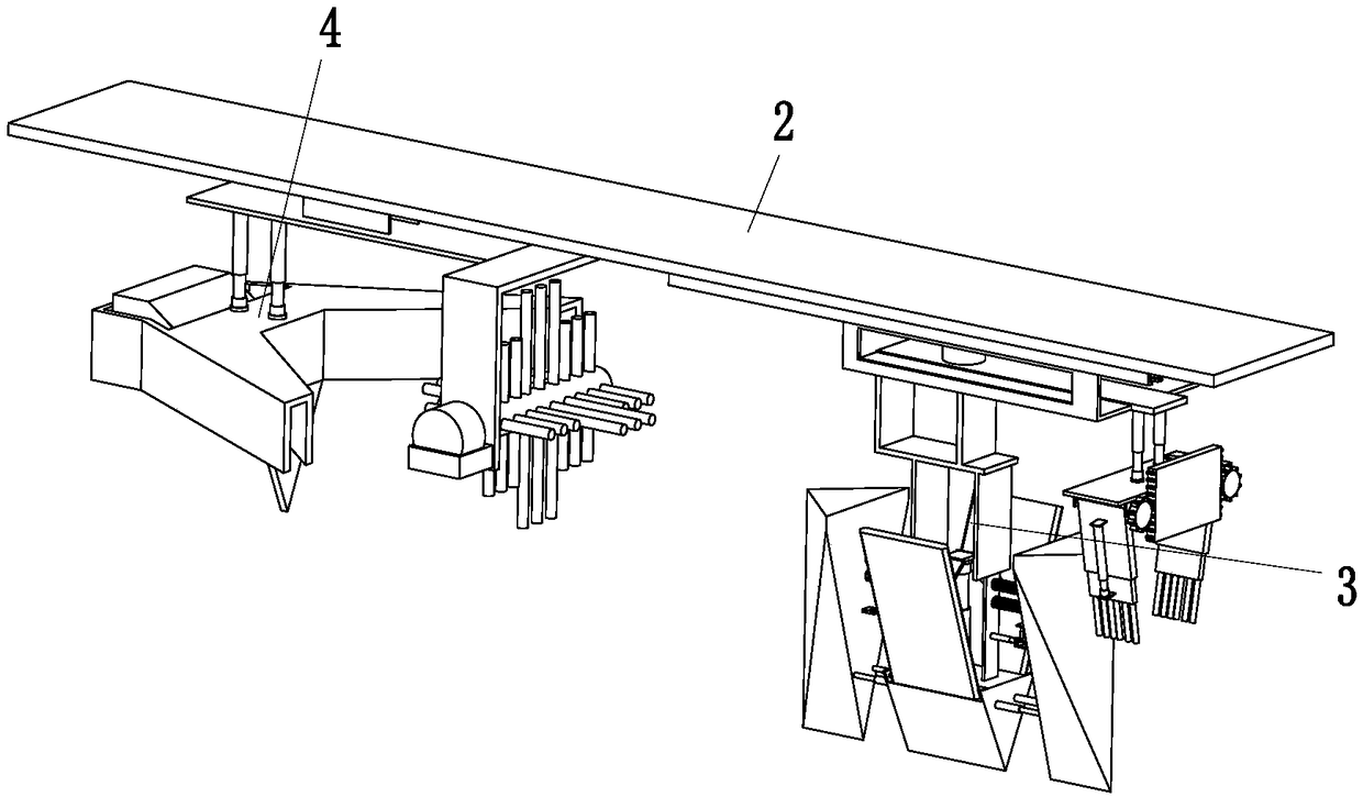
[0030] Such as Figure 1 to Figure 6 As shown, an aluminum-plastic plate automatic processing robot includes a main board 2, a slotting device 3 and a chip removal device 4. The right end of the main board 2 is equipped with a slotting device 3, and the left end of the main board 2 is equipped with a chip removal device 4. .

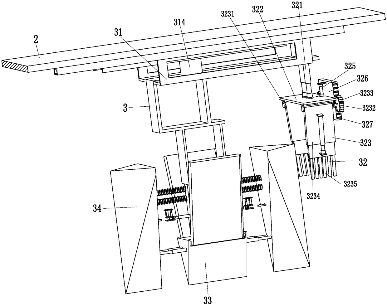
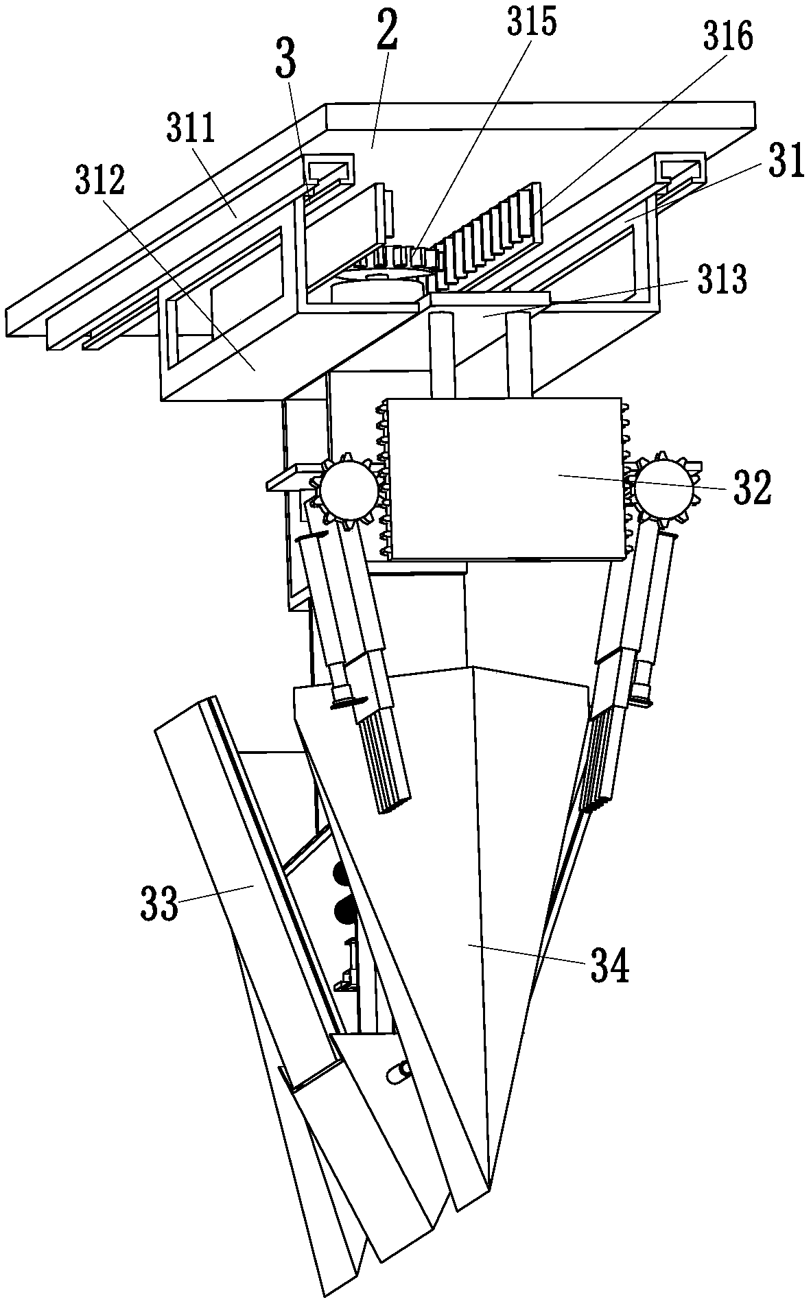
[0031] The slotting device 3 includes a reciprocating mechanism 31, a chip sweeping mechanism 32, a slotting mechanism 33 and two buffer slotting mechanisms 34, the reciprocating mechanism 31 is installed on the right end of the main board 2, and the lower end...


PUM


Abstract

The invention relates to an aluminum plastic plate automatic machining robot which comprises a main plate, a grooving device and a chip removal device. The grooving device is mounted at the right endof the main plate, and the chip removal device is mounted at the left end of the main plate. The aluminum plastic plate automatic machining robot can solve the problems that manual grooving is neededin the grooving process of an existing aluminum plastic plate, when grooving is started, a grooving knife directly grooves the aluminum plastic plate, consequently the life of the knife is prone to being affected, parts of grooves are not completely formed during manual grooving, chips are stacked on the two sides of the grooves to affect the working progress during grooving, an original positionis prone to being deviated during manual grooving, the chips generated after grooving are not cleared in time, consequently the consumed time is long, the labor intensity is large, and the efficiencyis low; and the functions of automatic grooving and chip collecting for the aluminum plastic plate can be achieved.

Description

technical field [0001] The invention relates to the technical field of processing aluminum-plastic panels, in particular to an automatic processing robot for aluminum-plastic panels. Background technique [0002] Aluminum-plastic panel is a new type of material, which has the characteristics of light weight, high strength, beautiful appearance, waterproof, fireproof, strong weather resistance, and easy processing. The aluminum-plastic panel is easy to break when directly bent, so it must be grooved before bending. However, the grooving process of the aluminum-plastic panel is cumbersome and complicated. The existing aluminum-plastic panel needs to be manually grooved. When grooving, part of the groove is not fully formed, and there will be scraps accumulated on both sides of the groove during grooving, which will affect the working process. Manual grooving is easy to deviate from the original position. The scraps generated after grooving are not cleaned in time, and the cons...

Claims


Application Information

Patent Timeline
Patent Type & Authority Applications(China)
IPC IPC(8): B23D79/00B23Q5/34B23Q11/00
CPCB23D79/00B23Q5/34B23Q11/0042B23Q11/0046B23Q11/005
Inventor 刘荷花
Owner 任丘市华泰铝业有限公司
Learn More