Laser cutting speed planning method, device, storage medium and computer equipment

A technology of speed planning and laser cutting, which is applied to laser welding equipment, welding equipment, metal processing equipment, etc., and can solve the problems of increasing laser cutting time and low laser cutting efficiency

Active Publication Date: 2020-12-25
HANS LASER TECH IND GRP CO LTD +1
View PDF9 Cites 0 Cited by
  • Summary
  • Abstract
  • Description
  • Claims
  • Application Information

AI Technical Summary

Problems solved by technology

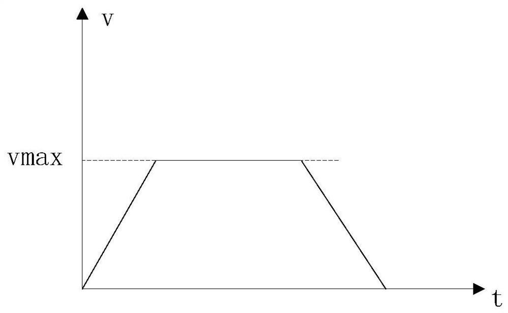
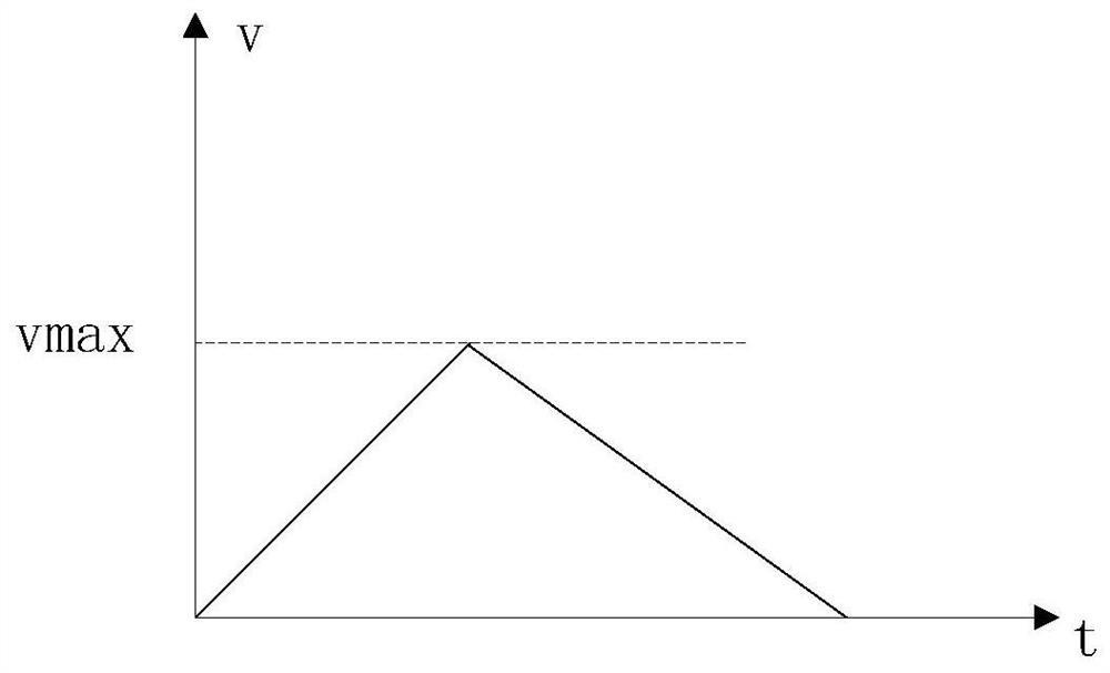
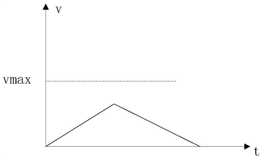
In addition, as shown in Figure 1(b) and Figure 1(c), considering the length of the cutting stroke path, the trapezoidal speed planning method may only include the acceleration-deceleration process
[0004] However, in the trapezoidal speed planning method, since each cutting stroke needs to be accelerated from zero and decelerated to zero at the end, it takes a certain amount of time to accelerate and decelerate the cutting speed in each cutting stroke, This increases the laser cutting time, which in turn leads to lower laser cutting efficiency

Method used


Image

  • Laser cutting speed planning method, device, storage medium and computer equipment
  • Laser cutting speed planning method, device, storage medium and computer equipment
  • Laser cutting speed planning method, device, storage medium and computer equipment

Examples


Embodiment Construction

[0030] In one embodiment, such as figure 2 As shown, a laser cutting speed planning method is provided, which includes the following steps:

[0031] Step S100, acquiring information of a current first cutting stroke in a cutting track to be processed, and information of a current second cutting stroke connected with the current first cutting stroke.

[0032] In this step, the cutting track to be processed refers to the track of laser cutting, which is generally composed of straight lines and / or arcs, and a straight line or arc represents a cutting stroke of a corresponding shape. Specifically, such as image 3 As shown, a schematic diagram of a laser cutting cutting track to be processed is provided, and the cutting track to be processed includes a cutting stroke L i , L i+1 and L i+2 . When performing speed planning, it is necessary to calculate the corner speed of the connection point of two adjacent cutting strokes. When calculating the corner speed of a certain conne...


PUM


Abstract

The invention relates to a laser cutting speed planning method and device, a storage medium and computer equipment. The laser cutting speed planning method includes the steps that information of a current first cutting stroke and information of a current second cutting stroke in a to-be-treated cutting track are acquired; the corner speed of a connection point is obtained according to the information of the current first cutting stroke and the information of the current second cutting stroke; the current first cutting stroke and the current second cutting stroke are updated, and the corner speeds of all cutting stroke connection points in the to-be-treated cutting track are obtained; and speed planning information of the to-be-treated cutting track is determined according to the information of all the cutting strokes and the corner speeds of all the cutting stroke connection points. The corner speeds of the connection points are obtained by calculating the information of the adjacent cutting strokes. In the laser cutting process, the final speed of the current cutting stroke only needs to be reduced to the corresponding corner speed, the speeds of the adjacent cutting strokes can be connected more smoothly, and therefore laser cutting time can be shortened and laser cutting efficiency is improved.

Description

technical field [0001] The invention relates to the technical field of laser cutting, in particular to a laser cutting speed planning method, device, storage medium and computer equipment. Background technique [0002] With the development of automation control technology, the application of laser cutting is becoming more and more extensive. Laser cutting refers to the use of high-power laser beams to irradiate the material to be cut, and the irradiated part of the material to be cut is heated and evaporated to form a narrow (such as about 0.1mm) slit. During the cutting process, the movement of the laser beam is controlled to control the formation position of the slit, so as to complete the laser cutting operation of the material to be cut. [0003] During the laser cutting process, the laser cutting speed needs to be planned to ensure the smooth and efficient control of the laser cutting motion. In the traditional technology, the trapezoidal speed planning method is used...

Claims


Application Information

Patent Timeline
Patent Type & Authority Patents(China)
IPC IPC(8): G05B19/416
CPCB23K26/70G05B19/4163
Inventor 封雨鑫陈焱高云峰
Owner HANS LASER TECH IND GRP CO LTD
Why Eureka
Try Eureka