
Automatic die cutting machine

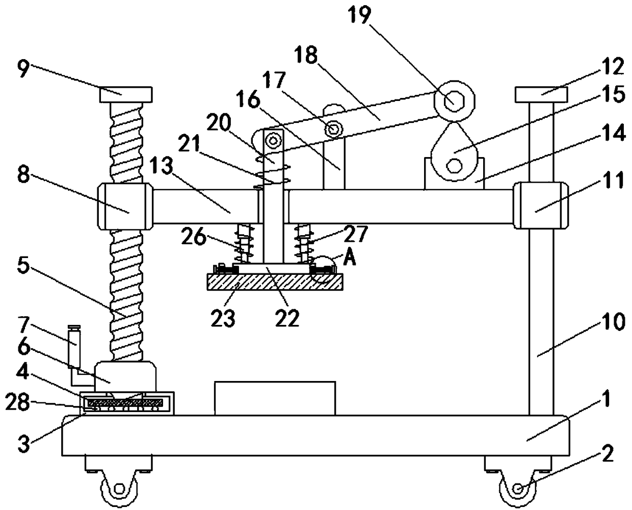
A die-cutting machine and cutting knife technology, which is applied in metal processing and other directions, can solve the problems of complex structure of the die-cutting machine and the inability to adjust the distance between the die-cutting knife and the cutting platform, and achieve the effect of simple structure and convenient replacement

Inactive Publication Date: 2018-12-21
肇庆高新区黑阳科技有限公司
View PDF0 Cites 3 Cited by
  • Summary
  • Abstract
  • Description
  • Claims
  • Application Information

AI Technical Summary

Problems solved by technology

[0003] However, the structure of the existing die-cutting machine is complicated, and the distance between the die-cutting knife and the cutting platform cannot be adjusted, and there are certain defects in the process of use.

Method used


Image

  • Automatic die cutting machine
  • Automatic die cutting machine

Examples


Embodiment Construction

[0016] The following will clearly and completely describe the technical solutions in the embodiments of the present invention with reference to the accompanying drawings in the embodiments of the present invention. Obviously, the described embodiments are only some, not all, embodiments of the present invention. Based on the embodiments of the present invention, all other embodiments obtained by persons of ordinary skill in the art without making creative efforts belong to the protection scope of the present invention.

[0017] In describing the present invention, it should be understood that the terms "upper", "lower", "front", "rear", "left", "right", "top", "bottom", "inner", " The orientation or positional relationship indicated by "outside", etc. is based on the orientation or positional relationship shown in the drawings, and is only for the convenience of describing the present invention and simplifying the description, rather than indicating or implying that the referre...


PUM


Abstract

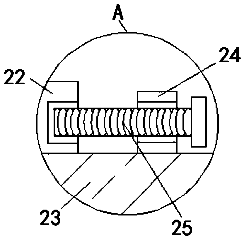
The invention belongs to the technical field of mechanical equipment, and particularly relates to an automatic die cutting machine. The automatic die cutting machine comprises a base, wherein four rolling wheels which are distributed in a rectangular mode are rotationally connected to the bottom of the base, one end of the top of the base is fixedly connected with a rotating sleeve, a rotating disc is rotationally connected in the rotating sleeve, a screw rod is fixedly connected to the top of the rotating disc, the screw rod penetrates through the inner top of the rotating sleeve and extendsoutwards, one end, close to the rotating sleeve, of the screw rod is fixedly sleeved with a sleeve, the sleeve is fixedly connected with a crank, one end, extending out of the screw rod, of the sleeveis rotatably sleeved with a threaded sleeve, the top of the screw rod is fixedly connected with a first limiting block, one end, far away from the rotating sleeve, of the top of the base is fixedly connected with a sliding rod, and a sliding sleeve sleeves the sliding rod in a sliding mode. According to the automatic die cutting machine, the sliding sleeve is arranged between the screw rod and the threaded sleeve, so that the cutting distance of the device can be freely adjusted according to a cutting platform, the structure is simple, and the defects existing in the using process are overcome.

Description

technical field [0001] The invention belongs to the technical field of mechanical equipment, in particular to an automatic die-cutting machine. Background technique [0002] The die-cutting machine is suitable for materials such as self-adhesive materials, protective films, electronic shielding materials, copper and aluminum foil, PVC / film mylar paper, double-sided adhesive tape or foam cotton, and LCD reflectors, diffusers, buffer sheets, Die-cutting equipment for materials such as glossy film or silicone tape. The die-cutting process is the most commonly used process for packaging printed matter. It is to use a die-cutter to form a die-cut plate according to the pattern required by the product design. Under the action of pressure , the forming process of rolling printed matter or other ring-packed blanks into the desired shape or cut marks. The creasing process uses a creasing knife or a creasing die to press the line marks on the sheet through the action of pressure, or u...

Claims


Application Information

Patent Timeline
Patent Type & Authority Applications(China)
IPC IPC(8): B26F1/40B26D7/26B26D5/16
CPCB26F1/40B26D5/16B26D7/2628
Inventor 姚碧莹
Owner 肇庆高新区黑阳科技有限公司
Learn More