
Automatic tool changing mechanism of automatic cutting bed

A technology of automatic tool change and cutting bed, applied in the field of cutting bed, can solve the problems of inconvenient operation and reduce work efficiency, and achieve the effect of saving working time, saving working time and convenient operation.

Pending Publication Date: 2018-12-21
潘声君
View PDF0 Cites 0 Cited by
  • Summary
  • Abstract
  • Description
  • Claims
  • Application Information

AI Technical Summary

Problems solved by technology

[0003] Usually, when using a cutting machine to cut materials of different specifications, the staff needs to manually replace the stamping dies, and when re-arranging the cutters, it is necessary to readjust the angle between the cutters and the materials, which is inconvenient to operate and reduces work efficiency

Method used


Image

  • Automatic tool changing mechanism of automatic cutting bed
  • Automatic tool changing mechanism of automatic cutting bed
  • Automatic tool changing mechanism of automatic cutting bed

Examples


Embodiment 2

[0056] Compared with the difference from Example 1, as Figure 6-Figure 8 As shown, the automatic tool change mechanism also includes a die magazine 11, the die magazine 11 is arranged on both sides of the body 1, a loading plate 12 is arranged on the die magazine 11, and guide sleeves are arranged on the corners of the die magazine 11 , The loading plate 12 is provided with a guide rod that runs through the guide sleeve. A number of stamping dies 37 are placed on the loading plate 12, and the body 1 is connected with a pusher 13 that drives the die storehouse 11 to move. The pusher 13 is set as the first driving cylinder, and the pusher 13 is electrically connected to the main control system.

[0057] A reference pin 14 that penetrates the loading plate 12 and the limit hole 102 is slidably provided in the knife mold library 11, and the loading plate 12 is provided with an accommodation block, and the accommodation block is provided with an accommodation groove 15, and the ac...


PUM


Abstract

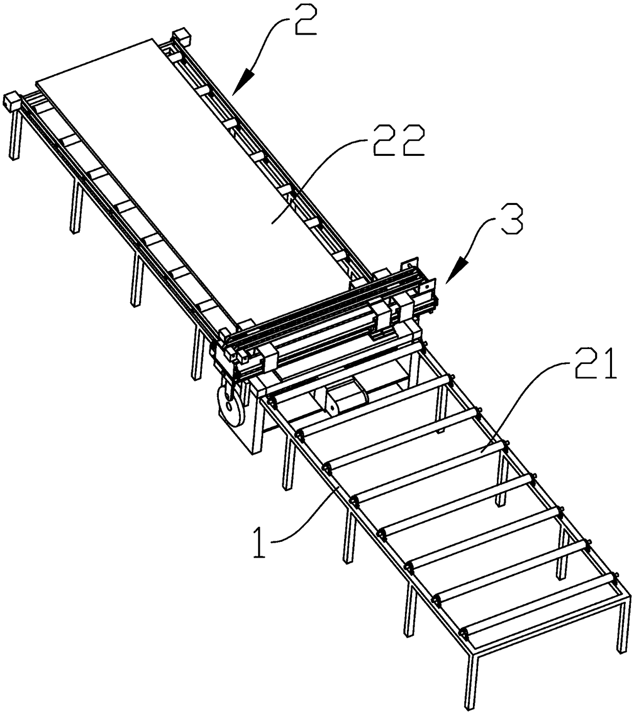
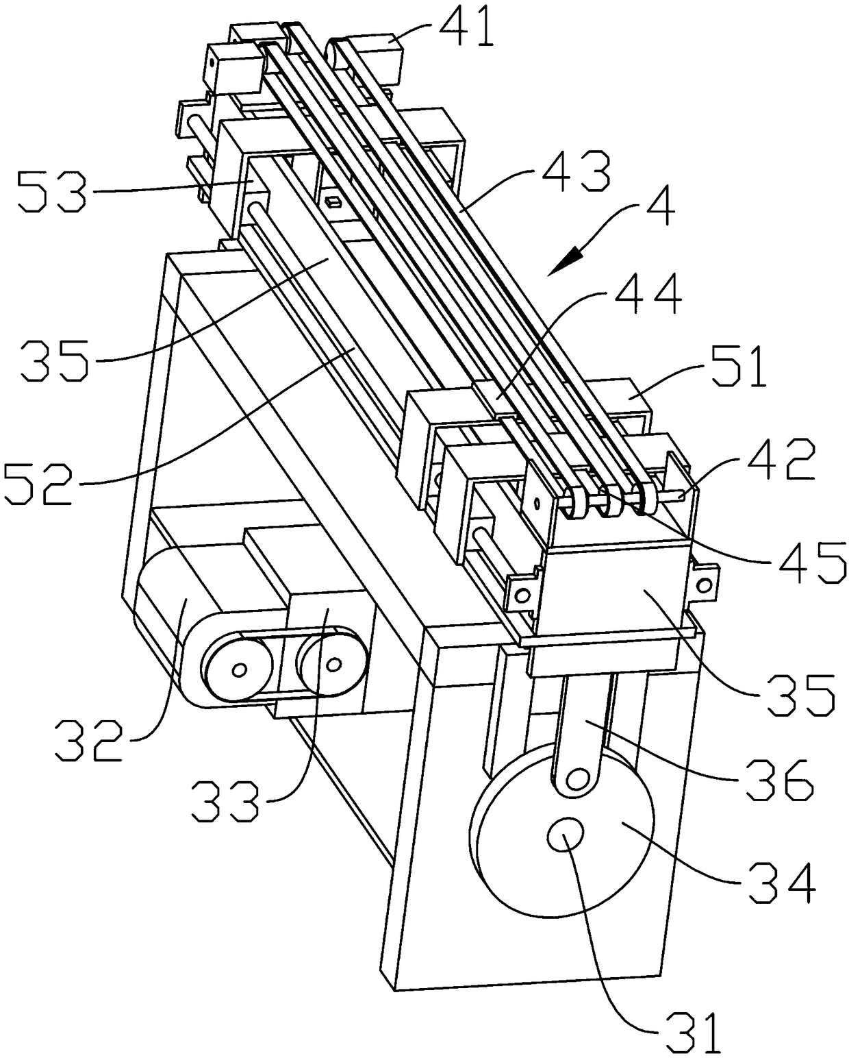
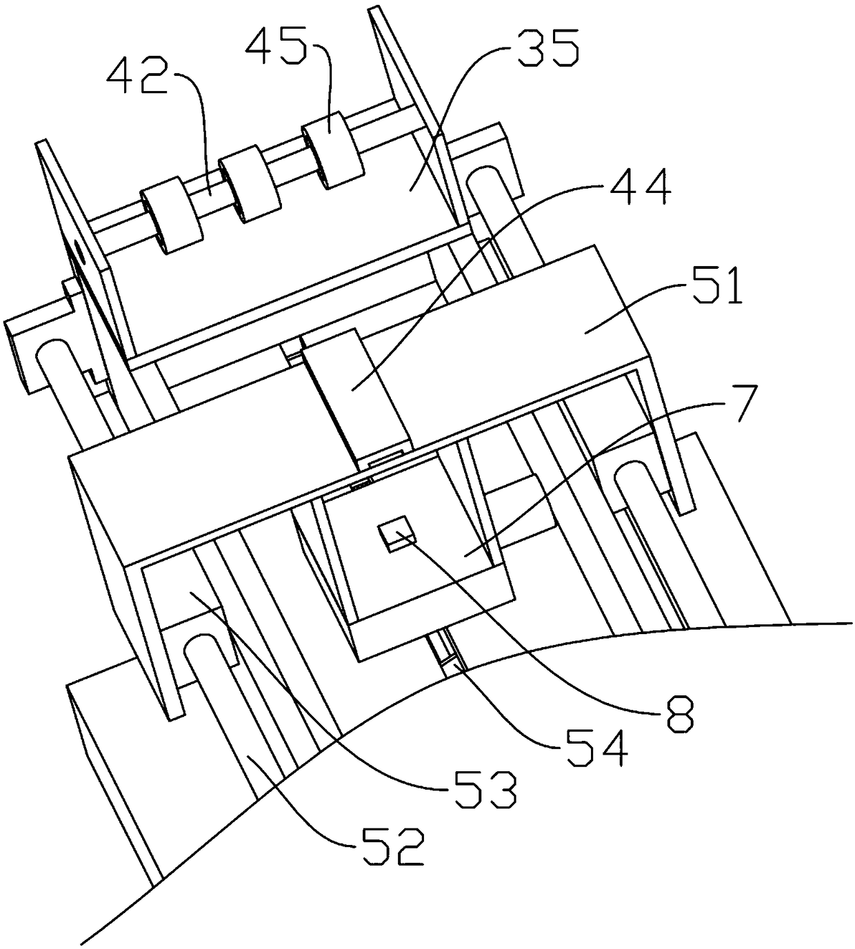
The invention discloses an automatic tool changing mechanism of an automatic cutting bed. The automatic tool changing mechanism of the automatic cutting bed comprises a machine body, a stamping mechanism and a main control system, wherein the stamping mechanism is arranged on the machine body; the main control system is electrically connected with the stamping mechanism; the stamping mechanism comprises a supporting platform arranged on the machine body; a gap is formed between the supporting platform and the machine body; a plurality of stamping cutting dies are slidingly connected to the supporting platform through connecting components; and rotating knife parts used for driving the stamping cutting dies to rotate are connected to the stamping cutting dies. The automatic tool changing mechanism of the automatic cutting bed has the advantage that the stamping cutting dies are automatically changed.

Description

technical field [0001] The invention relates to the technical field of cutting machines, in particular to an automatic tool changing mechanism for automatic cutting machines. Background technique [0002] With the prosperity of the garment industry, more and more garments and leather production are processed by cutting machines, which saves labor, improves production efficiency, and basically changes the production mode of traditional garment manufacturing. [0003] Usually, when using a cutting machine to cut materials of different specifications, the staff needs to manually replace the stamping dies, and when rearranging the cutters, the angle between the cutters and the materials needs to be readjusted, which is inconvenient to operate and reduces work efficiency. Contents of the invention [0004] The object of the present invention is to provide an automatic tool changing mechanism for an automatic cutting machine, which has the advantage of automatically changing pun...

Claims


Application Information

Patent Timeline
Patent Type & Authority Applications(China)
IPC IPC(8): B26F1/40B26F1/44B26D7/26
CPCB26D7/26B26F1/40B26F1/44B26D2007/2607
Inventor 潘声君
Owner 潘声君
Learn More