
Jolting-compacting isolation forming mould for building composite plate

A technology for composite panels and forming molds, which is applied in the field of construction composite panels, and can solve problems such as manual assembly, damage to partition walls, and difficulties in mold assembly and disassembly.

Active Publication Date: 2018-12-21
中铁建设集团中南建设有限公司
View PDF2 Cites 0 Cited by
  • Summary
  • Abstract
  • Description
  • Claims
  • Application Information

AI Technical Summary

Problems solved by technology

[0003] In order to solve the above problems, the present invention provides a vibration isolation forming mold for building composite boards, which can solve the problems that the existing polystyrene particle partition wall boards need to be manually assembled, difficult to assemble and disassemble, and require manual labor. Difficulties such as vibrating the mixture of partition wall panels, and removing the mold after the partition wall panels harden will cause damage to the partition wall panels; it can realize the function of vibrating and isolating the polystyrene particle partition wall panel mixture, and has the function of partition wall The board mold does not need to be assembled, the mold automatically adjusts the size, the mechanized vibration of the partition board mixture, and the mold removal after the partition board is hardened will not cause damage to the partition board, etc.

Method used


Image

  • Jolting-compacting isolation forming mould for building composite plate
  • Jolting-compacting isolation forming mould for building composite plate
  • Jolting-compacting isolation forming mould for building composite plate

Examples


Embodiment Construction

[0021] In order to make the technical means, creative features, goals and effects achieved by the present invention easy to understand, the present invention will be further described below in conjunction with specific illustrations. It should be noted that, in the case of no conflict, the embodiments in the present application and the features in the embodiments can be combined with each other.

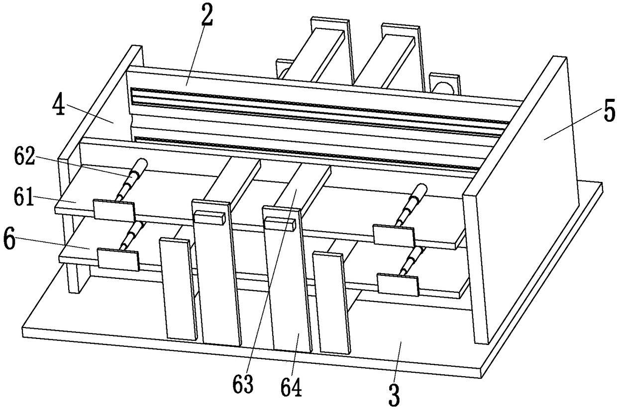
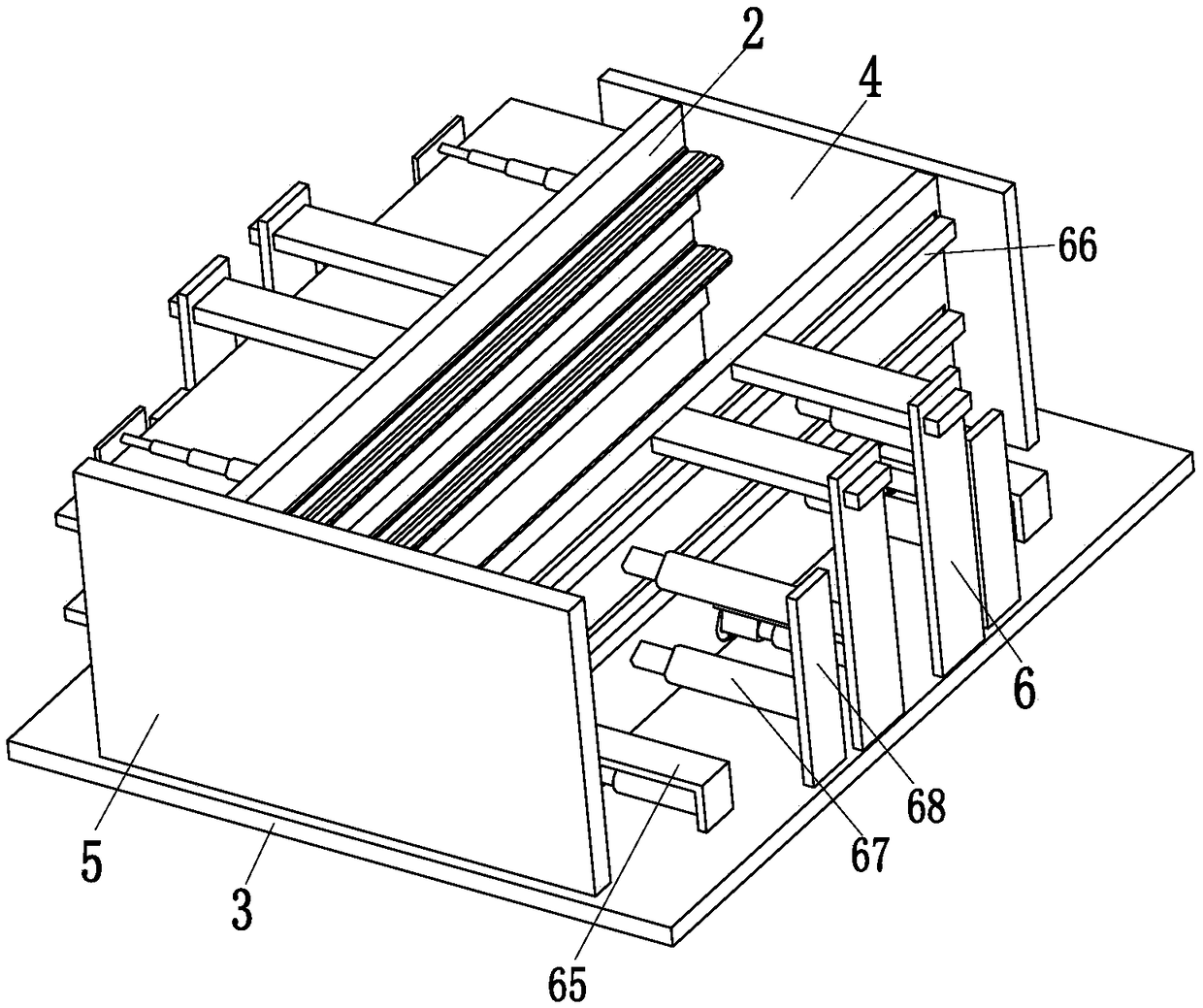
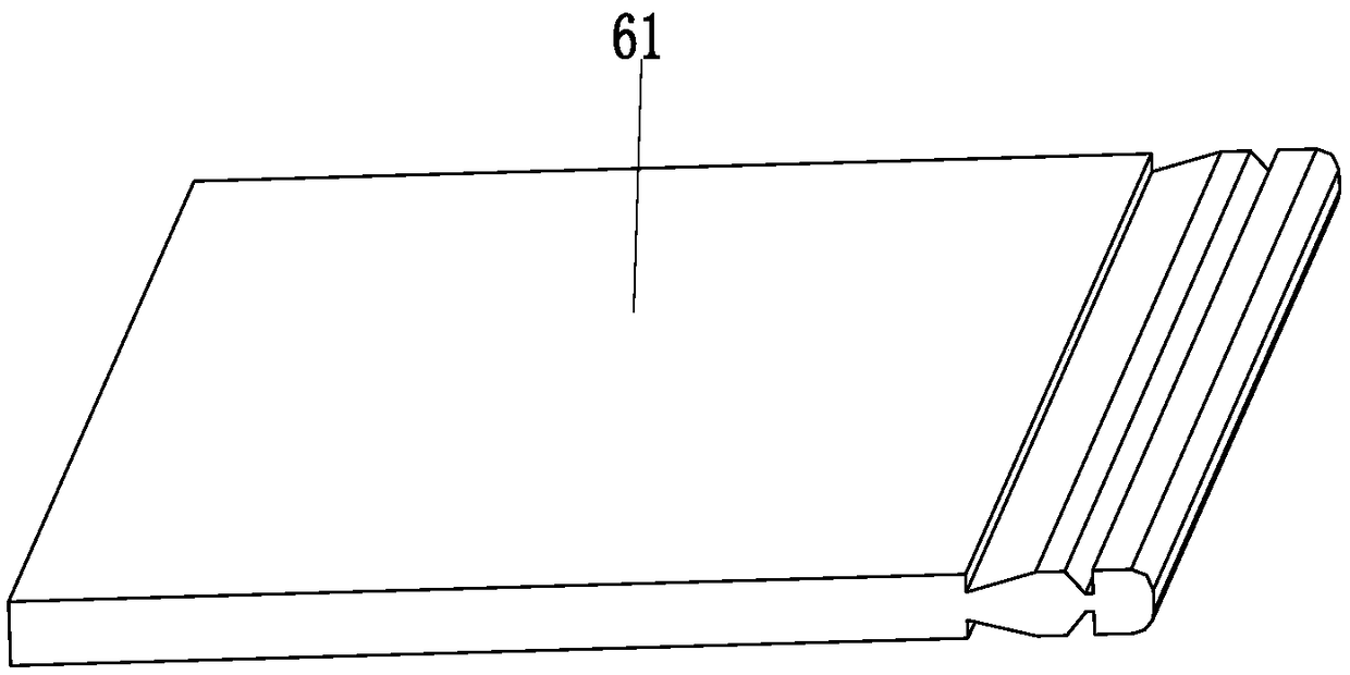
[0022]Such as Figure 1 to Figure 6 As shown, a building composite plate vibration isolation forming mold includes a transverse diaphragm 2, a forming chassis 3, a left vertical plate 4, a vertical vertical plate 5 and a vibration separation device 6, and the right end of the supporting forming chassis 3 A vertical vertical board 5 is installed on the top, and a transverse partition 2 is distributed on the front and rear sides of the left end of the vertical vertical board 5. The horizontal partition 2 cooperates with the vertical vertical board 5 through sliding friction. The left ...


PUM


Abstract

The invention relates to a jolting-compacting isolation forming mould for a building composite plate. The jolting-compacting isolation forming mould for the building composite plate comprises transverse partition plates, a forming base frame, a left vertical frame, a longitudinal vertical plate and jolting separation devices. The longitudinal vertical plate is installed at the top of the right endof the forming base frame, and the transverse partition plates are distributed on the front and rear sides of the left end of the longitudinal vertical plate correspondingly. The transverse partitionplates are matched with the longitudinal vertical plate in a sliding friction mode, and the left vertical plate is matched with the left ends of the transverse partition plates in a friction mode. The left vertical plate is mounted at the top of the left end of the forming base frame, and the jolting separation devices are mounted on the transverse partition plates. The jolting separation devicescomprise isolation plates, isolation multistage push rods, sliding connecting columns, sliding supporting columns, jolting mechanisms, separation mechanisms, position push rods and position connecting plates. The jolting-compacting isolation forming mould for the building composite plate can solve the existing problems that a partition plate mould needs to be assembled manually, the mould is difficult to assemble and disassemble, a partition plate mixture needs to be jolted and compacted manually, and after the partition plate is hardened, damage can be caused to the partition plate due to mould removal in the production of an existing polyphenyl granule partition plate.

Description

technical field [0001] The invention relates to the technical field of building composite board processing, in particular to a vibration isolation forming mold for building composite boards. Background technique [0002] Polystyrene particle partition wall board is a new type of building composite board composed of polystyrene particles, fly ash, cement and additives. Polystyrene particle partition wall board has the advantages of installing construction blocks, low cost, and less construction waste. The two sides of the benzene particle partition board are respectively provided with arc-shaped protrusions and arc-shaped grooves. The combination of the arc-shaped protrusions and the arc-shaped grooves increases the installation efficiency of the polystyrene particle partition wall board. The board is generally produced with a mold. After the mixture of polystyrene particle partition wall board is stirred evenly, it is put into the mold. After the belt is hardened and formed,...

Claims


Application Information

Patent Timeline
IPC IPC(8): B29C39/02B29C39/26B29C39/42
CPCB29C39/02B29C39/26B29C39/42
Inventor 缪心怡
Owner 中铁建设集团中南建设有限公司
Learn More