A semitransparent perovskite solar cell and a preparation method thereof

A solar cell and perovskite technology, applied in semiconductor/solid-state device manufacturing, circuits, photovoltaic power generation, etc., can solve problems that hinder the development and utilization of semi-transparent perovskite solar cells, and achieve transparency easily, increase transmittance, The effect of high processing efficiency

Active Publication Date: 2019-01-25
WUHAN UNIV OF TECH
View PDF5 Cites 9 Cited by
  • Summary
  • Abstract
  • Description
  • Claims
  • Application Information

AI Technical Summary

Problems solved by technology

Moreover, both methods face the problem of transparent conductive top electrodes. It is a big problem to prepare transparent conductive top electrodes on perovskite films, which hinders the further development and utilization of translucent perovskite solar cells.

Method used


Image

  • A semitransparent perovskite solar cell and a preparation method thereof
  • A semitransparent perovskite solar cell and a preparation method thereof
  • A semitransparent perovskite solar cell and a preparation method thereof

Examples


Embodiment 1

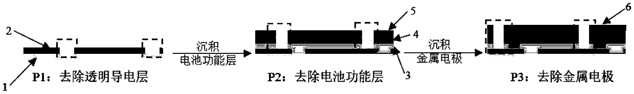
[0026] Such as figure 1 Shown, a kind of preparation method of translucent perovskite solar cell comprises the steps:

[0027] (1) Utilize an ultrafast laser to draw a line on a 5cm*5cm glass substrate containing an ITO transparent conductive layer, and cut the transparent conductive layer (P1). The tangent distance is 0.5mm, and the width of a single small battery is 0.5mm. The tangent processing parameters are: picosecond mode, repetition frequency of 200k Hz, laser power of 15W, galvanometer scanning speed of 1000mm / s, etching line width of 30μm; the substrate is cleaned after cutting;

[0028] (2) Scrape-coating a layer of tin oxide electron transport layer by Slot-die on the cleaned substrate;

[0029] (3) spin-coating perovskite and spiro-OMeTAD hole transport layer on the tin oxide electron transport layer;

[0030] (4) The functional layer (electron transport layer, perovskite light-absorbing layer and hole transport layer) is cut by ultrafast laser, but the transpar...

Embodiment 2

[0036] Such as figure 1 Shown, a kind of preparation method of translucent perovskite solar cell comprises the steps:

[0037] (1) Scribe a 10cm*10cm glass substrate containing an FTO transparent conductive layer with an ultrafast laser, and cut the transparent conductive layer (P1). The tangent distance is 0.4mm, and the width of a single small battery is 0.4mm. The tangent processing parameters are: picosecond mode, repetition frequency of 500k Hz, laser power of 14W, galvanometer scanning speed of 900mm / s, etching line width of 30μm; the substrate is cleaned after cutting;

[0038] (2) preparing a layer of tin oxide electron transport layer by chemical bath deposition on the cleaned substrate;

[0039] (3) Spin-coat perovskite light-absorbing layer and spiro-OMeTAD hole-transporting layer on the tin oxide electron-transporting layer;

[0040] (4) The functional layer (electron transport layer, perovskite light-absorbing layer and hole transport layer) is cut by ultrafast ...


PUM

PropertyMeasurementUnit
thicknessaaaaaaaaaa
transmittivityaaaaaaaaaa
energy conversion efficiencyaaaaaaaaaa

Abstract

The invention belongs to the field of perovskite solar cells, in particular to a semitransparent perovskite solar cell and a preparation method thereof. The preparation method comprises the followingsteps: a transparent conductive layer (P1) on a tangent line is peeled off by an ultrafast laser; Functional layers are deposited on the clean transparent conductive layer in turn, and the functionallayers on the tangent line are peeled off by ultrafast laser without damaging the transparent conductive layer (P2). The metal electrodes are deposited on the clean functional layer, and the metal electrode layer and the functional layer on the tangent line are peeled off by the ultrafast laser, and the positions of the transparent conductive layers (P3), P1, P2 and P3 are staggered mutually without damage; After the tangent is completed, the semi-transparent perovskite solar cell is prepared. The semi-transparent perovskite solar cell is proces by the laser, the active part of the cell is peel off by the laser, the active area of the module is reduced, and the transmittance of the module in the visible light range is remarkably increased.

Description

technical field [0001] The invention belongs to the field of perovskite solar cells, in particular to a translucent perovskite solar cell and a preparation method thereof. Background technique [0002] The semi-transparent cell can be used as building photovoltaic glass, which has a decorative effect while collecting energy, and realizes photovoltaic building integration, which has strong practical value. Currently commonly used crystalline silicon solar cell materials are difficult to produce transparent or translucent effects, and perovskite solar cells have become a hot spot for people to develop translucent cells because of their adjustable film layers, low cost and high efficiency. [0003] At present, the method for achieving translucency in perovskite solar cells is mainly to control the light-absorbing layer of perovskite, and to improve the light transmission of the device by reducing the thickness of perovskite and reducing the coverage of the film. The method of ...

Claims


Application Information

Patent Timeline
Patent Type & Authority Applications(China)
IPC IPC(8): H01L51/42H01L51/48H01L27/30
CPCH10K39/10H10K71/80H10K30/00Y02E10/549
Inventor 程一兵李天慧黄福志
Owner WUHAN UNIV OF TECH
Why Eureka
Try Eureka