Follow-up driving motor on permanent magnet direct drive ball mill

A direct-drive ball mill and drive motor technology, applied to electromechanical devices, synchronous motors with stationary armatures and rotating magnets, magnetic circuits, etc., can solve problems such as bore sweeping, cost increase, and permanent magnet consumption increase, and achieve reduction The number of inspections, the improvement of production efficiency, and the effect of long working hours

Pending Publication Date: 2022-01-14
河南全新机电设备有限公司
View PDF1 Cites 1 Cited by
  • Summary
  • Abstract
  • Description
  • Claims
  • Application Information

AI Technical Summary

Problems solved by technology

The eccentricity makes the gap between the stator core and the rotor core of the motor uneven, resulting in vibration and noise, increased loss, and increased temperature rise.
Therefore, in the manufacture of products, only by increasing the gap between the rotor and the stator to prevent the motor from sweeping, it is necessary to stop the machine frequently to calibrate and adjust the gap, and the gap between the stator and the rotor of the direct drive permanent magnet motor increases, the amount of permanent magnets will increase, and the cost will increase. Increase

Method used


Image

  • Follow-up driving motor on permanent magnet direct drive ball mill
  • Follow-up driving motor on permanent magnet direct drive ball mill
  • Follow-up driving motor on permanent magnet direct drive ball mill

Examples


Embodiment Construction

[0023] In describing the present invention, it should be understood that the terms "longitudinal", "transverse", "upper", "lower", "front", "rear", "left", "right", "vertical", The orientations or positional relationships indicated by "horizontal", "top", "bottom", "inner", "outer", etc. are based on the orientations or positional relationships shown in the drawings, and are only for the convenience of describing the present invention, rather than indicating or It should not be construed as limiting the invention by implying that a referenced device or element must have a particular orientation, be constructed, and operate in a particular orientation.

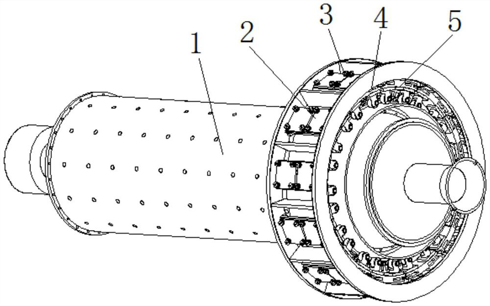
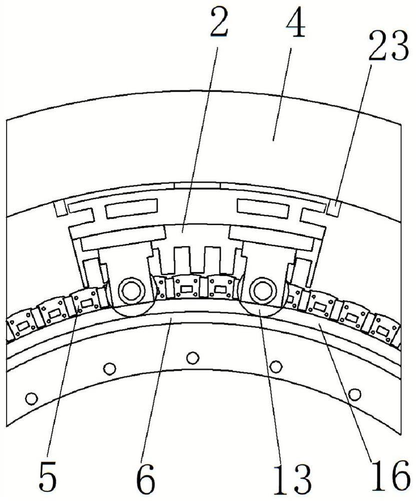
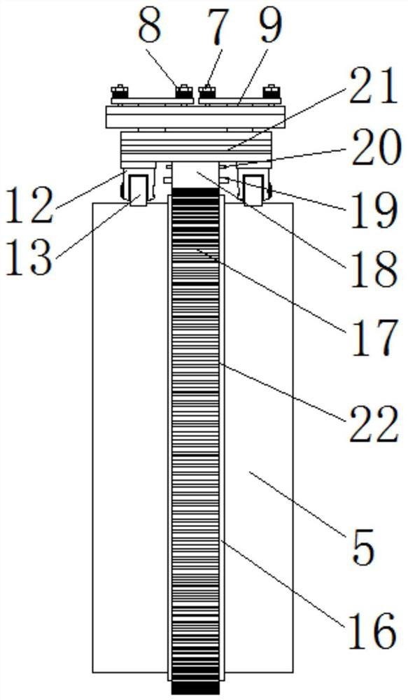
[0024]Describe in detail with reference to the accompanying drawings The present invention provides a technical solution: a servo drive motor on a permanent magnet direct drive ball mill, including a ball mill drum 1, a stator power mechanism 2, a rotor power mechanism 5, a support frame 4, and a drum 6 The stator power mechani...


PUM


Abstract

The invention discloses a follow-up driving motor on a permanent magnet direct drive ball mill, which comprises a ball mill roller, a stator power mechanism, a rotor power mechanism, a support frame and a rotary drum, wherein the stator power mechanism is connected to the centripetal inner side of the support frame, and the stator power mechanism comprises a stator silicon steel sheet, a coil, a stator shell, a guide wheel and an elastic pressure device; the rotor power mechanism comprises a rotor silicon steel sheet, a permanent magnet and a magnetic isolation aluminum plate; the rotor power mechanism is arranged on the outer surface of the rotary drum, the ball mill roller is arranged on the inner surface of the rotary drum, the guide wheel is arranged between the centripetal inner surface of the stator shell and the rotary drum, the elastic pressure device is arranged between the supporting frame and the centripetal outer surface of the stator shell, and the stator power mechanism and the rotor power mechanism form a follow-up driving motor. The structure is novel in design, the gap between the stator iron core and the rotor iron core can be controlled to be constant, the gap is designed to be very small, the use quantity of the permanent magnets is reduced, the manufacturing cost of the motor is reduced, the influence caused by eccentricity of the motor rotor is greatly reduced or avoided, and the operation is stable. The traditional concept is subverted, the motor can still operate normally in eccentric rotation operation, frequent correction of a gap between the stator iron core and the rotor iron core is avoided, frequent maintenance and replacement of a bearing are avoided, shutdown for maintenance after eccentricity is avoided, continuous working time is longer, the maintenance times are reduced, and the production efficiency is improved.

Description

technical field [0001] The invention relates to the technical field of ball mill driving motors, in particular to a servo drive motor on a permanent magnet direct drive ball mill. Background technique [0002] The ball mill is a kind of equipment for crushing materials. Its basic principle is to use the rotating force to lift the steel balls in the cylinder to a certain height and drop them on the materials. The materials are crushed by the mutual contact between the steel balls and the materials. The traditional ball mill needs to be equipped with a cumbersome transmission mechanism. In the traditional ball mill, the output shaft of the motor drives the pinion through the reducer, and the pinion drives the large gear to drive the drum to rotate. The Chinese patent application number is 201610640563.6, which discloses a permanent magnet synchronous motor direct-drive energy-saving ball mill. The rotating drum is provided with a feeding shaft and a discharging end at both end...

Claims


Application Information

Patent Timeline
Patent Type & Authority Applications(China)
IPC IPC(8): H02K21/02H02K21/14B02C17/24
CPCH02K21/021H02K21/14B02C17/24H02K2201/03
Inventor 张炳义尚勤贵冯桂宏王帅卞浩田吴鹏尚金铎高敏陈高敏尚金鸽
Owner 河南全新机电设备有限公司
Why Eureka
Try Eureka