Metallization method for solar cell fabrication

A solar cell and metallization technology, applied in circuits, photovoltaic power generation, electrical components, etc., to achieve the effect of low cost, reduced production cost, and low cost

Inactive Publication Date: 2012-01-25
RENA
View PDF1 Cites 2 Cited by
  • Summary
  • Abstract
  • Description
  • Claims
  • Application Information

AI Technical Summary

Problems solved by technology

Due to the characteristics of the metal paste and the limitations of various printing methods on the process system, the size of the prin

Method used


Image

  • Metallization method for solar cell fabrication
  • Metallization method for solar cell fabrication
  • Metallization method for solar cell fabrication

Examples


Embodiment Construction

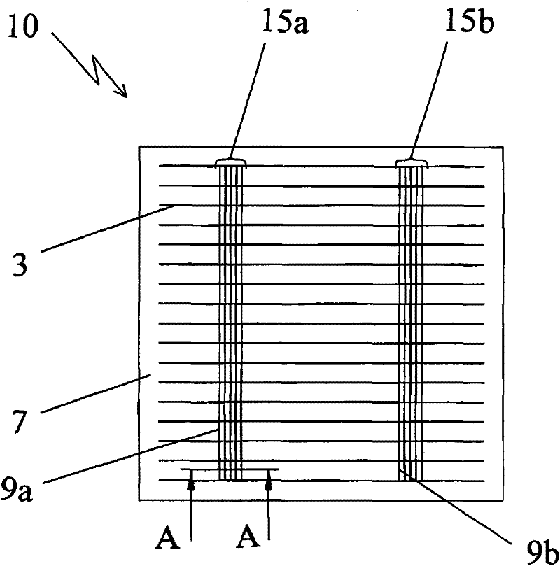
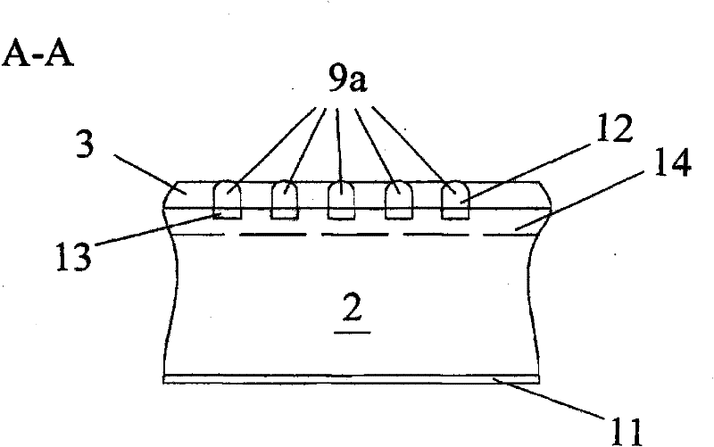
[0051] Such as figure 2 Shown is a schematic diagram of a first embodiment of a solar cell 10 of the present invention. The solar cell 10 has an electrode network comprising electrode metal fingers 3 and bus bars 15a, 15b. The bus bars 15a, 15b respectively include a plurality of bus bar metal fingers 9a, 9b arranged at intervals. Each bus bar 15a, 15b respectively includes bus bar metal fingers 9a, 9b which are locally gathered and arranged at intervals.

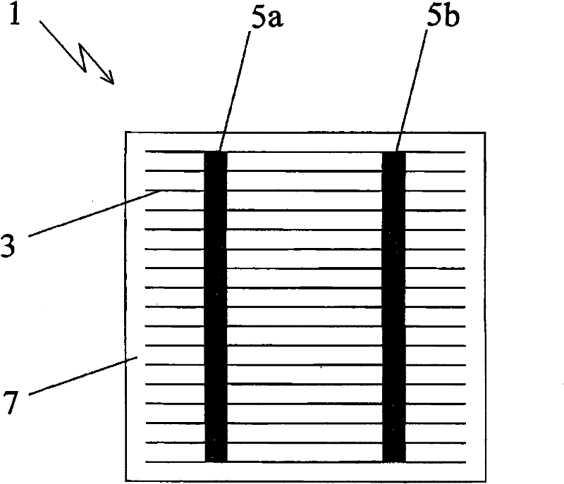
[0052] and figure 1 Compared with the shown prior art solar cell with electrode mesh, according to figure 2 An advantage of the solar cell of the present invention of the embodiment is that the solar cell produced has less shading of the active solar cell surface 7 . In this embodiment, the less shielding is mainly due to the fact that the bus bars 15a, 15b are respectively formed by the bus bar metal fingers 9a, 9b which are spaced apart from each other. As mentioned above, this less shadowing does not degrade fill ...


PUM


Abstract

The invention provides a metallization method for solar cell fabrication, which comprises the steps of: one layer of dopant-containing mediums (56) is coated (30) at positions which are on a solar cell substrate (2) and are to be metallized; carrying out locally heating (32) on the positions which are on the solar cell substrate (2) and are to be metallized, so as to enable dopant to be locally diffused to the internal part of the solar cell substrate (2) from the dopant-containing mediums (56); and conducting electro-deposition processing (34) on metals (12) at the positions (60a and 60b) which are to be metallized and are at a position (32) on which local doped diffusion processing is conducted, wherein the positions (60a and 60b) which are to be metallized are used as electrodes for the electro-deposition processing (34).

Description

technical field [0001] The present invention relates to a metallization method for the manufacture of solar cells. Background technique [0002] A primary consideration in the metallization (metallization) process of solar cell substrates in the manufacture of solar cells is cost. In the industrial production of solar cells, a special metal paste is usually coated on the light-receiving surface of the solar cell by a printing method such as screen printing, gravure printing or roller printing. Due to the characteristics of the metal paste and the limitations of various printing methods on the process system, the size of the printed components, especially the size of the metal electrode fingers or lines (bus connection lines) cannot be reduced to the desired range. In addition, during the coating process, a photolithographic method (photolithographic) is used to add a mask with an appropriate structure. Using these methods, not only can reduce the need for metallized surfac...

Claims


Application Information

Patent Timeline
IPC IPC(8): H01L31/05H01L31/0224H01L31/18
CPCY02E10/50Y02P70/50
Inventor 哈特穆特 纳斯鲍墨尔
Owner RENA
Why Eureka
Try Eureka