Water gap rotary cutting jig

A nozzle and fixture technology, applied in the field of nozzle rotary cutting fixtures, can solve the problems of poor safety, long processing cycle, product damage, etc., and achieve the effect of efficient and thorough rotary cutting, not easy to leak, and stable quality

Pending Publication Date: 2018-12-21
SHENZHEN SILVER BASIS TECH
View PDF0 Cites 0 Cited by
  • Summary
  • Abstract
  • Description
  • Claims
  • Application Information

AI Technical Summary

Problems solved by technology

The manual method is for workers to scrape off the nozzle with a blade, which is inefficient and the quality of the finished product is uneven, and it is prone to defects such as incomplete removal of the nozzle and product damage; the semi-automatic method is for the worker to cut off the exposed nozzle on the product first, and then use the milling machine to remove the remaining Nozzle, complex process, long processing cycle, does not match the efficiency of injection molding, and has defects such as serious dust pollution and poor safety

Method used


Image

  • Water gap rotary cutting jig
  • Water gap rotary cutting jig
  • Water gap rotary cutting jig

Examples


Embodiment 1

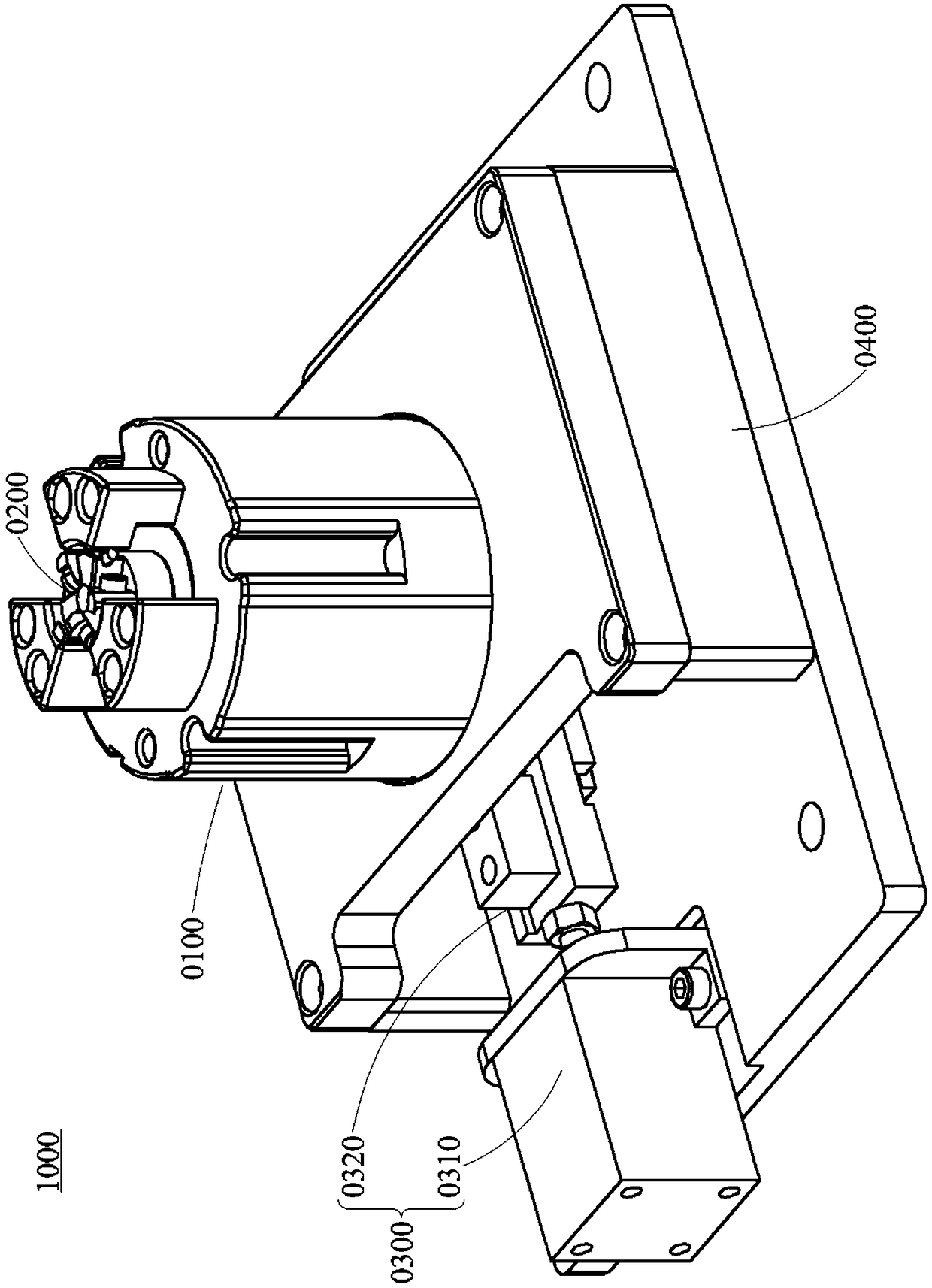
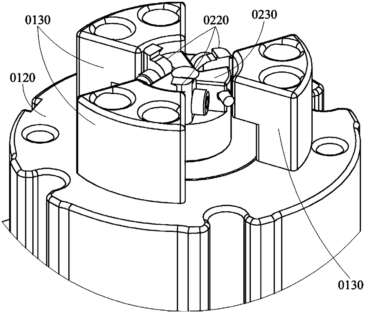
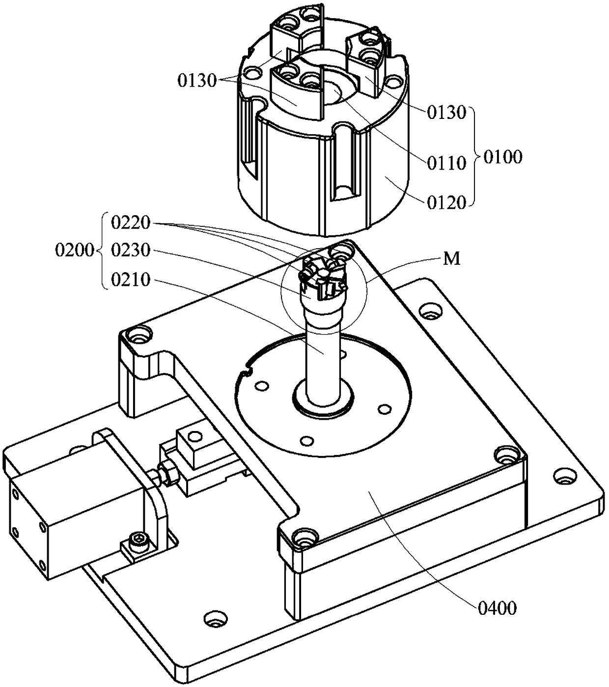
[0038] Please refer to Figure 1~6 , this embodiment discloses a nozzle rotary cutting fixture 1000, the nozzle rotary cutting fixture 1000 includes a positioning bottom mold 0100, a spindle unit 0200 and a driving unit 0300, which are used to achieve safety, reliability, simple operation, excellent processing efficiency and quality Nozzle rotary cutting.

[0039] First of all, the product P to be processed is a blank removed from the injection molding machine after injection molding, and the nozzle has not been cleaned. It can be understood that the product P to be processed includes the product body P(a) and the nozzle P(b), and the product body P(a) and the nozzle P(b) are still connected. The shape of the product body P(a) is determined according to actual product requirements. Exemplarily, the product body P(a) is a cylindrical plastic shell. Correspondingly, the nozzle P(b) overlaps the opening of the end of the cylindrical plastic housing (for example, the center of t...

Embodiment 2

[0060] Please refer to Figure 8-9 , this embodiment discloses a nozzle rotary cutting device U, the nozzle rotary cutting device U includes a worktable 2000 and an electric control system 3000, and the nozzle rotary cutting fixture 1000 and the top tightening unit introduced in Embodiment 1 are set on the workbench 2000 4000, realizing fast and reliable nozzle rotary cutting.

[0061] Workbench 2000 provides the main operating place for nozzle rotary cutting, and provides the installation basis for other components. Exemplarily, the workbench 2000 has a work chamber 2100 with one side open, providing a safe and reliable place for operation. The nozzle rotary cutting jig 1000 and the clamping unit 4000 are both arranged in the working chamber 2100 to obtain the safety protection of the working chamber 2100 . The working chamber 2100 is well sealed to avoid accidents caused by accidental touches, and is also conducive to ensuring a good working environment for the nozzle rota...


PUM


Abstract

The invention discloses a water gap rotary cutting jig which comprises a positioning bottom die, a spindle unit and a drive unit; the positioning bottom die is used for positioning and bearing a product to be processed; the product to be processed comprises a product body and a water gap; the spindle unit is rotatably kept on the positioning bottom die and comprises a rotary spindle and a rotary cutting tool; the rotary cutting tool is arranged at one end, close to the product to be processed, of the rotary spindle; a cutting edge of the rotary cutting tool faces a connection portion of the product body and the water gap in a rotation direction of the rotary spindle; and the drive unit is used for driving the rotary spindle to rotate. The water gap rotary cutting jig provided by the invention can efficiently perform water gap rotary cutting, is complete in rotary cutting and stable in quality, has the advantages of cleanness and environmental protection in processing process and high safety and realizes matching with the efficiency of an injection molding procedure.

Description

technical field [0001] The invention belongs to the technical field of injection molding, in particular, it is a nozzle rotary cutting fixture. Background technique [0002] In injection molding, high-temperature molten plastic needs to enter the mold cavity from the nozzle of the injection molding machine through the nozzle to form a product with the desired shape. After the product is injection molded, the nozzle will be connected to the product and ejected together with the product. It is necessary to remove the spout on the product in order to obtain the finished product with the final product form. [0003] At present, the removal of nozzles generally adopts a full manual method or a semi-automatic method. The manual method uses workers to scrape off the nozzle with a blade, which is inefficient, and the quality of the finished product is uneven, and it is prone to defects such as incomplete removal of the nozzle and product damage; the semi-automatic method is to fir...

Claims


Application Information

Patent Timeline
Patent Type & Authority Applications(China)
IPC IPC(8): B29C45/38
CPCB29C45/382
Inventor 高国利贾宇霖冯金兴曾德健邹汉泳
Owner SHENZHEN SILVER BASIS TECH
Why Eureka
Try Eureka