Anti-cavitation installation for tails of flaring gate piers of stepped spillway

A technology of overflow dam and wide tail pier, which is applied in water conservancy engineering, marine engineering, coastline protection and other directions to reduce the possibility of damage, improve energy dissipation rate, and accelerate dissipation.

Inactive Publication Date: 2018-12-21
KUNMING UNIV OF SCI & TECH
View PDF5 Cites 3 Cited by
  • Summary
  • Abstract
  • Description
  • Claims
  • Application Information

AI Technical Summary

Problems solved by technology

[0005] The invention provides an anti-cavitation facility at the tail of the wide tail pier of a stepped overflow dam, which

Method used


Image

  • Anti-cavitation installation for tails of flaring gate piers of stepped spillway
  • Anti-cavitation installation for tails of flaring gate piers of stepped spillway
  • Anti-cavitation installation for tails of flaring gate piers of stepped spillway

Examples


Embodiment 1

[0026] Embodiment 1: A cavitation facility 6 at the end of the wide tail pier of a stepped overflow dam is applied to a key water conservancy and hydropower project focusing on power generation, taking into account flood control, irrigation and other comprehensive utilization. The maximum working head of the spillway of the power station is 105m, and the design is uniform The slope of the ladder is 53°, and the maximum single-width flow rate is 178m 3 / s.m.

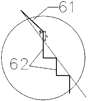
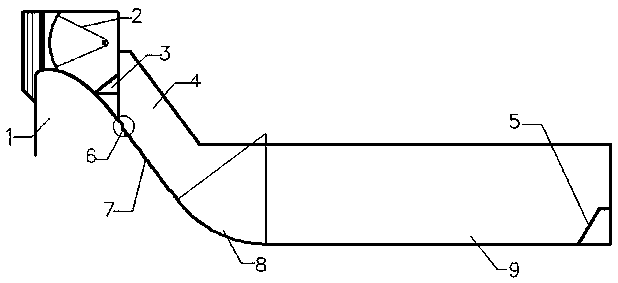
[0027] In this embodiment, the combined energy dissipator of the ridge + new transitional steps is applied to hydraulic flood discharge structures with high water head and large single-width flow, and its structure is as follows Figure 5 , Figure 6 As shown, it includes a riser 61 and a new transition step 62 arranged behind the wide tail pier 3 . The shape of the ridge 61 is "triangular", and its angle θ is 9°≤θ≤11.3°. In this embodiment, three specific angles are selected, which are 9°, 10°, and 11.3° respectively, ...

Embodiment 2

[0030] Embodiment 2: An anti-cavitation facility 6 at the end of the wide pier of a stepped overflow dam is used for steps with an average step gradient of 53°, and is used in flood discharge structures with high water head and large single-width flow.

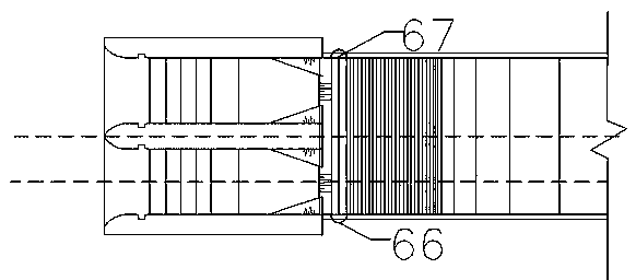
[0031] The air defense facility at the end of the wide tail pier of a stepped overflow dam in this embodiment has a structure such as Figure 7 , 8 As shown, it includes a riser 61 and a new transition step 62 arranged behind the wide tail pier 3 . The shape of the ridge 61 is "triangular", and its angle θ is 9°≤θ≤11.3°. In this embodiment, three specific angles are selected, which are 9°, 10°, and 11.3° respectively, and its height h=1m. Followed by a corbel-shaped aeration tank 65 transition ladder 62, the transition ladder is made up of 2 steps with a height of 2m and a width of 1.5m, and a corbel-shaped aeration tank 65, such as Figure 7 , 8 , the corbel-shaped aeration groove 65 refers to the backward extension distan...


PUM


Abstract

The invention discloses an anti-cavitation installation for the tails of flaring gate piers of a stepped spillway. The anti-cavitation installation adopts sluice chambers which combine sluice piers with the flaring gate piers and which are provided with inlets larger than outlets, and can increase the compression capacity on water flows by virtue of the flaring gate piers to horizontally contractand vertically stretch the discharged water flows for downstream ski jumping so that streams of ski-jump water jets aerate and collide with each other in the air, thereby improving the energy dissipation effect of the flaring gate piers. A flip bucket at the tails of the flaring gate piers can deflect water flowing out of the sluice chambers from a spillway surface so that the posterior spillway surface forms a waterless area. The shape of novel transition steps with aeration tanks is utilized to change the area size and shape of an aeration cavity, and ventilation holes and ventilation shaftsare also used for aeration to increase the aeration amount at the spillway surface so as to enable the spillway surface which is most prone to be damaged by cavitation erosion and cavitation to perform reasonable aeration and reduce the possibility of damage. Steps behind the cavity are exactly the falling points of the front edges of the water jets, and the friction resistance effect of the steps on the water flows is utilized to accelerate the dissipation of the flow discharge energy by the steps; and then a reversed arc section and a stilling basin are utilized to further dissipate the energy.

Description

technical field [0001] The invention relates to a cavitation facility at the tail of the wide pier of a stepped overflow dam, which belongs to the field of flood discharge and energy dissipation in water conservancy and hydropower projects. Background technique [0002] In recent years, with the development of dam-building technology in our country, stepped overflow dams have been widely used in small and medium-sized projects at home and abroad. In the traditional energy dissipation method, the high energy dissipation rate is only limited to 40m 3 (s·m) small single-width flow, in the case of large single-width flow and high head (single-width flow q>40m 3 (s m)), due to the coverage of the overflow tongue, the step surface is difficult to ventilate, and cavitation damage may occur, so it cannot be applied to flood discharge structures with high water head and large single-width flow. [0003] According to the existing engineering practice and numerous tests, aerated c...

Claims


Application Information

Patent Timeline
IPC IPC(8): E02B8/06
CPCE02B8/06
Inventor 董丽艳杨具瑞
Owner KUNMING UNIV OF SCI & TECH
Why Eureka
Try Eureka