An electric bridge scaffolding

A technology of scaffolding and electric bridge, which is applied in the field of construction engineering, can solve the problems of electric bridge scaffolding, such as the inability to guarantee the safety, the long installation process, and the slow progress of the project, so as to reduce the difficulty of work, reduce the workload and improve safety. Effect

Active Publication Date: 2020-11-03
GUANGDONG BOZHILIN ROBOT CO LTD
View PDF6 Cites 0 Cited by
  • Summary
  • Abstract
  • Description
  • Claims
  • Application Information

AI Technical Summary

Problems solved by technology

[0002] Scaffolding is a feature of modern architecture. Generally, when building a house, it is necessary to build a scaffold first, and then inside the scaffolding, the house that needs to be built can be used for the construction of secondary structures, glass curtain walls, metal curtain walls, etc. For exterior wall decoration projects, the current scaffolding generally has a steel pipe structure and is fixed with cross thread knots. Due to the large volume and high height of the house, a lot of steel pipes are required for the scaffolding, and because the steel pipes are built layer by layer, Therefore, there is a relatively large gap in the supply of goods on the upper floor, which is usually completed by an external working tower crane. In this case, when the workload is heavy, the tower crane is particularly prone to fatigue, and the operation is difficult. Manually transporting items requires a lot of manpower. Due to the limitations of scaffolding, electric bridge scaffolding has appeared on the market, which reduces the burden of tower cranes and the use of manpower to a certain extent.
[0003] In the prior art, the connection between steel pipe structures is troublesome, which makes the installation process time-consuming, which leads to slow progress of the project, and the safety of the electric bridge scaffolding cannot be guaranteed. If the chain breaks during the construction of high-rise buildings, it will cause falling. building accidents, resulting in major safety accidents

Method used


Image

  • An electric bridge scaffolding
  • An electric bridge scaffolding
  • An electric bridge scaffolding

Examples


Embodiment Construction

[0027] In order to deepen the understanding of the present invention, the present invention will be further described below in conjunction with the examples, which are only used to explain the present invention, and do not constitute a limitation to the protection scope of the present invention.

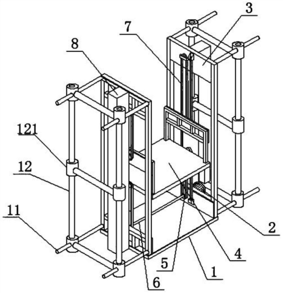
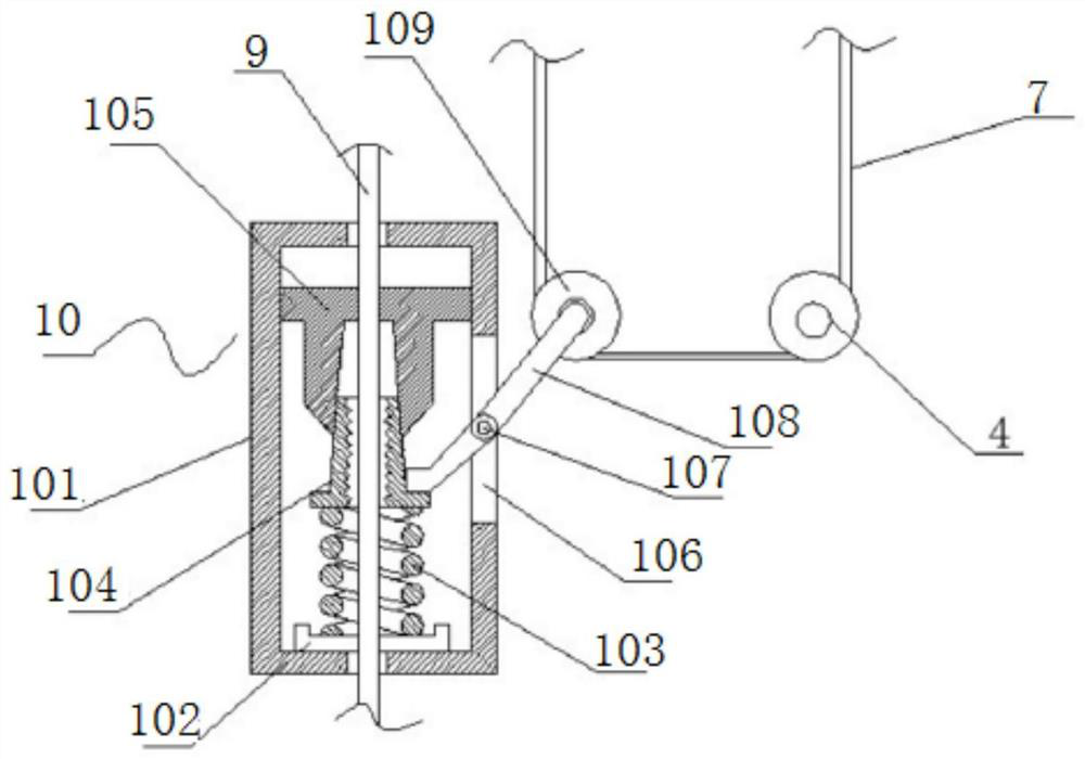
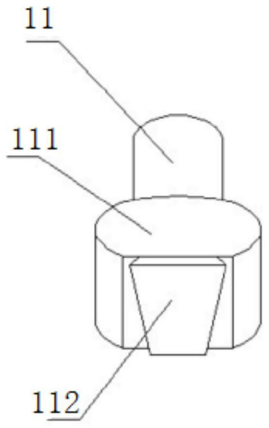
[0028] according to Figure 1-4 The electric bridge scaffolding shown includes a lower frame 1, a motor 2, an upper frame 3 and an operating platform 4, the motor 2 is installed in the middle of the left side of the lower frame 1, the upper frame 3 is welded on the top of the lower frame 1, and the lower frame 1 There is an operation platform 4 on the inside of the upper frame 3, through the lifting of the operation platform 4, the speed of material transportation can be accelerated, the workload of manual transportation is reduced, the difficulty of tower crane work is reduced, and the construction is safe and reliable. The lower frame 1 and the upper frame 3 are about Outer frames ...


PUM


Abstract

The invention provides an electric bridge-type scaffold. The electric bridge-type scaffold comprises a lower framework, a motor, an upper framework and an operating platform; the motor is installed inthe middle of the left side of the lower framework, the upper framework is welded to the top of the lower framework, and the operating platform is arranged at the inner sides of the lower framework and the upper framework; outer frames are welded to the outer sides of the left and right sides of the lower framework and the upper framework, upright rods are vertically welded to the interiors of the outer frames, and anti-falling mechanisms are arranged at the outer sides of the upright rods; transverse rods are inserted in the outer sides of the lower framework and the upper framework, vertical rods are inserted between the transverse rods, six fixed pulleys are arranged and equally divided into two groups in two lines, the fixed pulleys in the middles of the inner sides of the left and right sides of the lower frame are connected through a connecting rod, and all the fixed pulleys are connected through chains. According to the electric bridge-type scaffold, through the arrangement ofa series of structures, the scaffold has the advantages of being convenient to install, high in safety and the like.

Description

technical field [0001] The invention relates to the field of construction engineering, in particular to an electric bridge scaffold. Background technique [0002] Scaffolding is a feature of modern architecture. Generally, when building a house, it is necessary to build a scaffold first, and then inside the scaffolding, the house that needs to be built can be used for the construction of secondary structures, glass curtain walls, metal curtain walls, etc. For exterior wall decoration projects, the current scaffolding generally has a steel pipe structure and is fixed with cross thread knots. Due to the large volume and high height of the house, a lot of steel pipes are required for the scaffolding, and because the steel pipes are built layer by layer, Therefore, there is a relatively large gap in the supply of goods on the upper floor, which is usually completed by an external working tower crane. In this case, when the workload is heavy, the tower crane is particularly prone...

Claims


Application Information

Patent Timeline
Patent Type & Authority Patents(China)
IPC IPC(8): E04G1/15E04G1/22E04G1/24
CPCE04G1/152E04G1/22E04G1/24
Inventor 孙军杨泓斌张亮亮江海峰王云燕
Owner GUANGDONG BOZHILIN ROBOT CO LTD
Why Eureka
Try Eureka