Differential reducer

A split reducer and reducer technology, applied in transmission parts, belts/chains/gears, mechanical equipment, etc., to achieve the effects of small friction coefficient, compensation of coaxiality error, and relaxation of load impact

Pending Publication Date: 2018-12-21
CSR ZIYANG TRANSMISSION
View PDF0 Cites 1 Cited by
  • Summary
  • Abstract
  • Description
  • Claims
  • Application Information

AI Technical Summary

Problems solved by technology

[0004] The purpose of the present invention is to provide a transfer reducer to solve the problem that the existing transfer reducer cannot quickly and effectively cool down

Method used


Image

  • Differential reducer
  • Differential reducer
  • Differential reducer

Examples


Embodiment

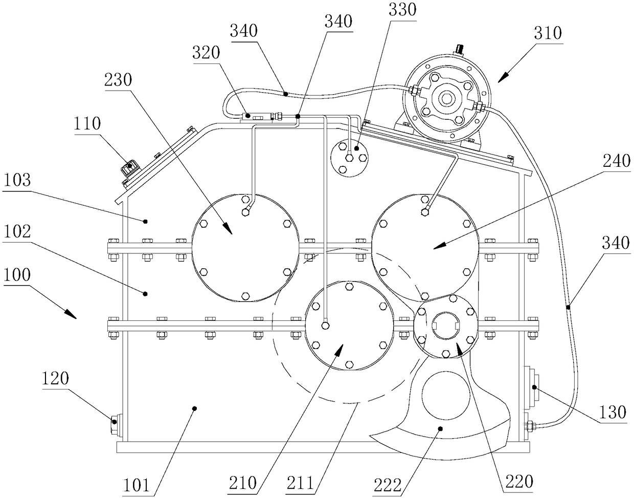
[0040] Please refer to figure 1, a transfer reducer, including: a sealed box 100, a reduction system and a lubrication system. The box body 100 includes a lower box body 101, a middle box body 102 and an upper box body 103 from bottom to top. The middle box body 102 is connected with the lower box body 101 and the upper box body 103 by bolts, and the connection positions are sealed. The bottom of the box 100 , that is, the lower box 101 has lubricating oil, the bottom side wall of the lower box 101 is provided with an oil drain plug 120 , and the middle side wall of the lower box 101 is provided with a cursor 130 . The side wall of the upper box body 103 is provided with a valve-type ventilation cap 110 .

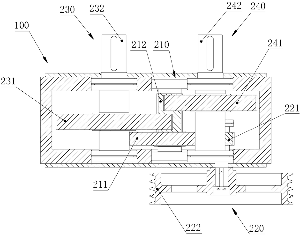
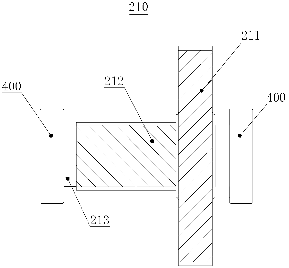
[0041] Please refer to Figure 1 to Figure 6 , the reduction system includes an intermediate shaft assembly 210, an input shaft assembly 220, a low-speed output shaft assembly 230, and a high-speed output shaft assembly 240. The intermediate shaft assembly 210 and the inp...


PUM


Abstract

The invention discloses a differential reducer, and belongs to the technical field of reducers. The differential reducer includes a box body, a gear reduction system and a lubrication system, whereinthe gear reduction system includes an intermediate shaft assembly, an input shaft assembly, a low speed output shaft assembly and a high speed output shaft assembly, a transmission gearwheel in the intermediate shaft assembly is partially placed in lubricating oil, the lubrication system includes a thin oil lubricating station, an oil distributor and a connector seat, the thin oil lubricating station is connected with the bottom of the box body and the oil distributor, oil outlets of the oil distributor communicate with the joints between each assembly and the box body and the connector seat correspondingly, and perforated oil tubes on the connecting seat are placed above gears on the low speed output shaft assembly and the high speed output shaft assembly. According to the differential reducer, the thin oil lubricating station provides fast circulating fluidity for the lubricating oil, the transmission gearwheel drives the lubricating oil to splash while stirring the lubricating oil,thus the heat dissipation performance of the differential reducer is improved, and the oil temperature can be effectively lowered.

Description

technical field [0001] The invention relates to the technical field of reducers, in particular to a transfer reducer. Background technique [0002] The split reducer for chemical engineering machinery is used in raw material mixing and processing equipment in chemical enterprises. It is required that the two output shafts of the split reducer rotate in the same direction and maintain a certain speed ratio relationship. Among the two output shafts, the one with the faster speed is the high-speed output Shaft, the slower rotating speed is the low-speed output shaft. The raw material mixing and processing equipment operates continuously on the assembly line, requiring the reducer to be able to operate continuously for a long time. During the operation of the equipment, due to the heavy dust in the environment, the temperature rise of the reducer is large, so the reducer is required to have good sealing, excellent lubrication and heat dissipation. [0003] At present, during t...

Claims


Application Information

Patent Timeline
Patent Type & Authority Applications(China)
IPC IPC(8): F16H57/023F16H57/04F16H57/028F16H57/021
CPCF16H57/023F16H57/021F16H57/028F16H57/0423F16H57/0458
Inventor 罗晓龙
Owner CSR ZIYANG TRANSMISSION
Why Eureka
Try Eureka