Movable type LED illuminating lamp device

An LED lighting, mobile technology, applied in lighting devices, lighting devices, lighting auxiliary devices, etc., can solve the problems of inability to adjust height and angle, small illumination range, inconvenient movement, etc., to avoid cable length constraints, Long service life and improved usability

Inactive Publication Date: 2018-12-21
芜湖通全电子电器科技创业有限公司
View PDF0 Cites 7 Cited by
  • Summary
  • Abstract
  • Description
  • Claims
  • Application Information

AI Technical Summary

Problems solved by technology

[0002] LED lighting is a lighting fixture made of the fourth-generation green light source LED. It is widely used in various indications, displays, decorations, backlights, ordinary In the fields of lighting and urban night scenes, most of the existing LED lighting lamps are simple in structure and single in function, and they are all fixed, not only inconvenient to move, but also unable to adjust their height and angle according to needs. Poor, which is very unsuitable for construction sites with complex environments. In addition, most LED lights rely on mains power to work. Not only the work cost is high, but also easily restricted by the length of the cable, and the scope of use is small. less practical

Method used


Image

  • Movable type LED illuminating lamp device
  • Movable type LED illuminating lamp device
  • Movable type LED illuminating lamp device

Examples


Embodiment Construction

[0023] The following will clearly and completely describe the technical solutions in the embodiments of the present invention with reference to the accompanying drawings in the embodiments of the present invention. Obviously, the described embodiments are only some of the embodiments of the present invention, not all of them. Based on the embodiments of the present invention, all other embodiments obtained by persons of ordinary skill in the art without making creative efforts belong to the protection scope of the present invention.

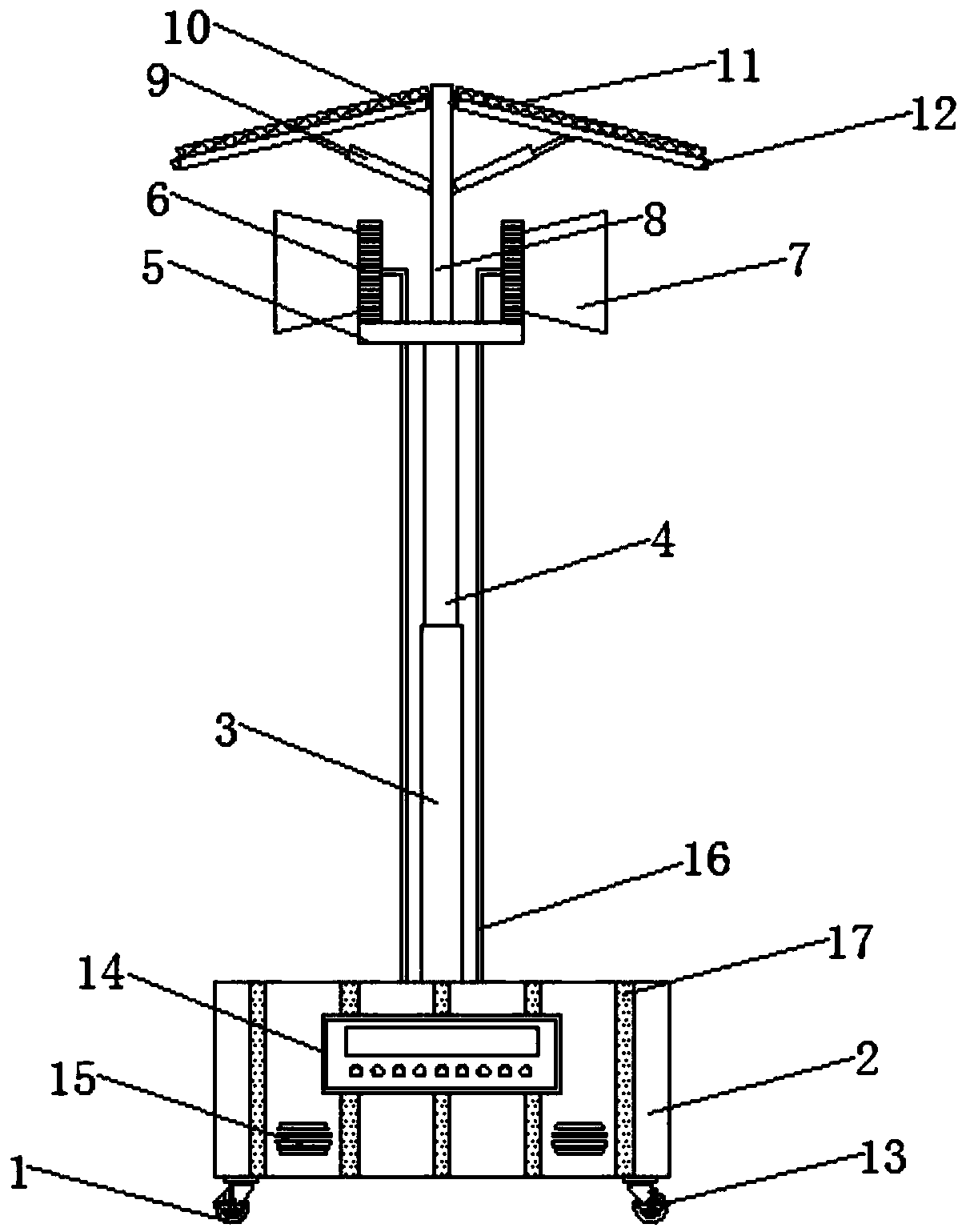
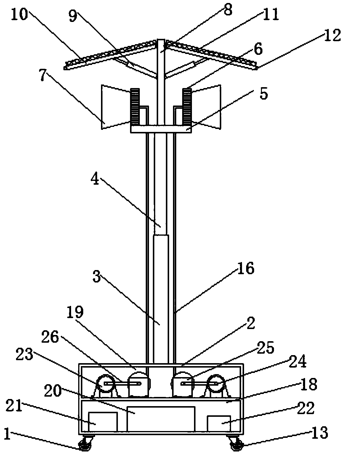
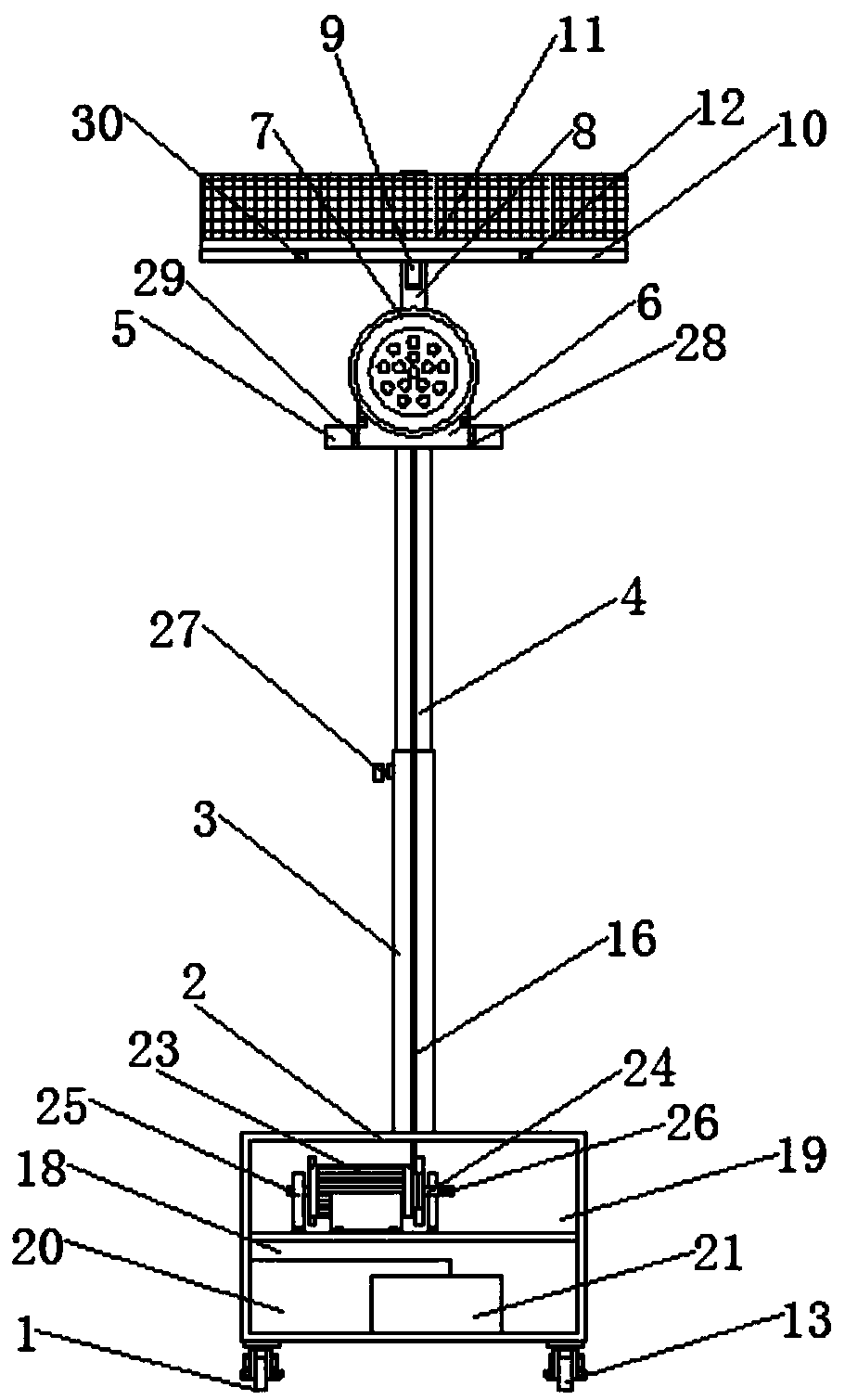
[0024] see Figure 1-5, the present invention provides a technical solution: a mobile LED lighting device, including a device body 1, a base 2, a fixed rod 3, a telescopic rod 4, a mounting plate 5, a support plate 6, an LED lighting lamp 7, and a support rod 8 , electric push rod 9, bottom plate 10, solar panel 11, LLS08-J photosensitive sensor 12, casters 13, operation panel 14, music player 15, cable 16, reflective strip 17, control box 18, dr...


PUM


Abstract

The invention discloses a movable type LED illuminating lamp device. A base is arranged at the bottom of a device body, the top of the base is provided with a fixing rod, the top of the fixing rod isfixedly connected with a telescopic rod, a mounting plate is mounted at the top of the telescopic rod, grooves are formed in the two sides of the mounting plate, a rotating shaft is mounted inside thegrooves, a 24H-12 motor is installed at one end of the rotating shaft, the other end of the rotating shaft is provided with a shaft seat, a supporting plate is mounted in the middle of the rotating shaft, an LED illuminating lamp is mounted on one side of the supporting plate, a supporting rod is mounted in the middle of the top of the mounting plate, an electric push rod is arranged in the middle of the supporting rod, a bottom plate is arranged at the top end of the electric push rod, and foot wheels are mounted at the bottom of the base. According to the device, the supporting plate is fixedly connected with the 24H-12 motor through the rotating shaft, the 24H-12 motor can drive the supporting plate to rotate through the rotating shaft, so that illumination angles of the LED illuminating lamp can be adjusted, flexibility and convenience are realized, illumination areas are expanded, meanwhile, manual operation is also avoided, and intelligent degrees of the device body are improved.

Description

technical field [0001] The invention relates to the technical field of LED lighting lamps, in particular to a mobile LED lighting lamp device. Background technique [0002] LED lighting is a lighting fixture made of the fourth-generation green light source LED. It is widely used in various indications, displays, decorations, backlights, ordinary In the fields of lighting and urban night scenes, most of the existing LED lighting lamps are simple in structure and single in function, and they are all fixed, not only inconvenient to move, but also unable to adjust their height and angle according to needs. Poor, which is very unsuitable for construction sites with complex environments. In addition, most LED lights rely on mains power to work. Not only the work cost is high, but also easily restricted by the length of the cable, and the scope of use is small. Less practical. [0003] Therefore, it is necessary to design a mobile LED lighting device to solve such problems. Con...

Claims


Application Information

Patent Timeline
Patent Type & Authority Applications(China)
IPC IPC(8): F21S9/03F21V21/06F21V21/15F21V21/22F21V23/04F21V27/00F21V31/00F21V33/00H02S20/30F21Y115/10
CPCF21S9/035F21V21/06F21V21/15F21V21/22F21V23/0464F21V27/00F21V31/00F21V33/0056F21Y2115/10H02S20/30Y02E10/50
Inventor 汤佳季一全
Owner 芜湖通全电子电器科技创业有限公司
Why Eureka
Try Eureka