
A color matching instrument of optimized color difference resolution and testing method

A testing method and optimal technology, applied in optical instrument testing, testing optical performance, testing of machine/structural components, etc., can solve the problem of poor ability to distinguish chromatic aberration, increase the difficulty of segmentation and identification of image processing algorithms, and cannot improve system positioning. and measurement accuracy

Pending Publication Date: 2018-12-21
GUANGDONG UNIV OF TECH
View PDF14 Cites 2 Cited by
  • Summary
  • Abstract
  • Description
  • Claims
  • Application Information

AI Technical Summary

Problems solved by technology

The selection of the light source is the key point that affects the quality of the entire image acquisition system from the physical layer. If an inappropriate light source is selected so that the region of interest (ROI, hereinafter referred to as the foreground region) in the image is optimally separated from the background region, the image processing will be increased. Algorithm segmentation and identification are difficult, and at the same time, the accuracy of system positioning and measurement cannot be improved
Using the color difference between the foreground and the background can realize highlighting the foreground and suppressing the background. The traditional method is to select the region of interest by color parameters, that is, use a color industrial camera to configure a white light source to directly segment the effect obtained by taking pictures, such as region segmentation. This method has poor ability to distinguish color difference

Method used


Image

  • A color matching instrument of optimized color difference resolution and testing method
  • A color matching instrument of optimized color difference resolution and testing method
  • A color matching instrument of optimized color difference resolution and testing method

Examples


Embodiment Construction

[0058] The content of the present invention will be further described below in conjunction with specific examples, but it should not be construed as a limitation of the present invention.

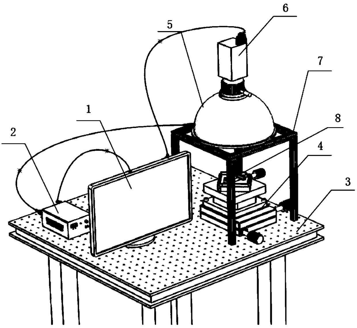
[0059] Such as figure 1 As shown, a color difference optimal resolution color matching instrument includes an image processing system 1, a light source controller 2, a black and white industrial camera 6, a dome light source 5 and a platform, and the dome light source 5 includes a red light source, a green light source and A blue light source, the platform includes a base platform 3 and a mobile platform 4, the image processing system 1 and the mobile platform 4 are fixed on the base platform 3, and an aluminum profile is placed above the mobile platform 4 Support 7, the support 7 fixes the dome light source 5, the lens of the black-and-white industrial camera 6 is coaxially installed on the top of the dome light source 5, and the dome light source 5 forms reflected light through the dome, ...


PUM


Abstract

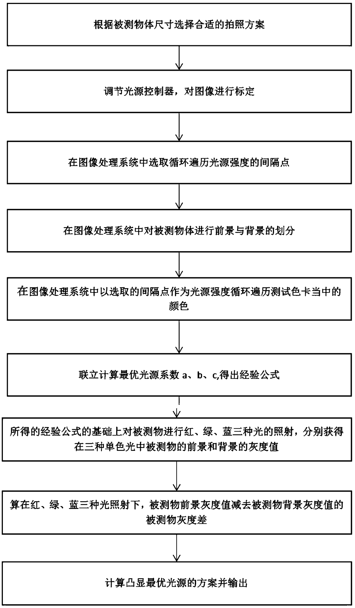
The invention belongs to the technical field of light distribution for machine vision, and discloses a color matching instrument of optimized color difference resolution and testing method. The invention comprises an image processing system, a light source controller, a black-and-white industrial camera, a dome light source and the platform, wherein the light source controller is connected to theimage processing system; the image processing system comprises an image acquisition module and a color temperature calculation module; the input end of the light source controller is connected to thedome light source; the output of the light source controller is connected to the image acquisition module; and the black-and-white industrial camera is connected to the image acquisition module. The lens of the black-and-white industrial camera is coaxially mounted on top of the dome light source, which forms reflected beam after reflection from the dome to illuminate the moving platform. The method can calibrate the image processing system to delineate the foreground and background of the testing object and calculate the gray scale of the foreground and background, from which the scheme of light distribution with optimal color difference is obtained and outputted.

Description

technical field [0001] The invention belongs to the technical field of machine vision light source light distribution, and more specifically relates to a color difference optimal resolution color matching instrument and a testing method thereof. Background technique [0002] At present, the core process in the field of machine vision is image acquisition and processing, and image quality is extremely critical to the overall vision system. The selection of the light source is the focus of affecting the quality of the entire image acquisition system from the physical layer. If an inappropriate light source is selected, the region of interest (ROI, hereinafter referred to as the foreground region) in the image can be optimally separated from the background region, which will increase the quality of the image processing. Algorithm segmentation and identification are difficult, and at the same time, the accuracy of system positioning and measurement cannot be improved. Using the...

Claims


Application Information

Patent Timeline
Patent Type & Authority Applications(China)
IPC IPC(8): G01M11/02H04N5/232H04N9/04
CPCG01M11/00H04N23/67H04N23/10
Inventor 邓凯元雷亮李燕秋阮杨徐初东周金运
Owner GUANGDONG UNIV OF TECH
Learn More