Coring device for roadbed soil and method for installing moisture sensor by using coring device

A technology for coring device and roadbed soil, which is applied to measuring devices, instruments, scientific instruments, etc., can solve the problems of easy loosening of soil core samples, easy damage to moisture sensors of backfill, and easy water ingress of moisture sensors, so as to prevent loose soil samples. Effect

Inactive Publication Date: 2018-12-21
HARBIN INST OF TECH
View PDF13 Cites 4 Cited by
  • Summary
  • Abstract
  • Description
  • Claims
  • Application Information

AI Technical Summary

Problems solved by technology

[0006] The purpose of the present invention is to solve the problem that the soil compactness of the probe test site in the prior art often fails to meet the compactness requirements of the roadbed, which affects the test accuracy of the volumetric moisture content. In the process of lowering the moisture sensor with the soil core sample, The soil core sample is easy to loose, and the moisture sensor is easy to be damaged during the layered compaction backfilling process, and the moisture sensor is prone to water ingress during the long-term monitoring process, and then provides a coring device for roadbed soil and a method for installing a moisture sensor using the coring device

Method used


Image

  • Coring device for roadbed soil and method for installing moisture sensor by using coring device
  • Coring device for roadbed soil and method for installing moisture sensor by using coring device
  • Coring device for roadbed soil and method for installing moisture sensor by using coring device

Examples


specific Embodiment approach 1

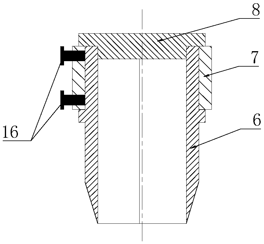
[0030] Specific implementation mode one: combine Figure 1-Figure 4 Illustrate this embodiment, the coring device for subgrade soil described in this embodiment, it includes blade 6, restraining ring 7, spacer 8 and a plurality of top wires 16; Process the limit protrusion of the restraint ring, the restraint ring 7 is an annular sleeve body, the side wall of the annular sleeve body is provided with a plurality of jacking wires 16, the restraining ring 7 is sleeved on the top of the knife body 6, each jacking wire 16 The top is supported on the outer wall of the knife body 6, and the cushion block 8 covers are contained on the knife body 6 and the restraining ring 7.

[0031] In this embodiment, the inner diameter of the blade body 6 is 70mm, and the blade angle of the blade body 8 is 17°.

specific Embodiment approach 2

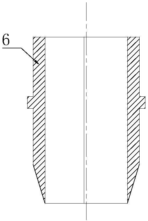
[0032] Specific implementation mode two: combination Figure 1-Figure 4 Describe this embodiment, the coring device for subgrade soil described in this embodiment, the knife body 6 is formed by two semi-annular cylinders fastened together to form an annular cylinder, and the inner walls of the two sides of one semi-annular cylinder are respectively processed with One vertical protrusion, the inner wall of the two sides of the other semi-annular cylinder is respectively processed with a vertical groove corresponding to the vertical protrusion, and each vertical protrusion on the two sides of the semi-annular cylinder corresponds to It is arranged in a vertical groove on both sides of the other semi-annular cylinder, and the vertical protrusions and vertical grooves are arranged correspondingly to increase the matching performance of the two semi-annular cylinders and prevent the two semi-annular cylinders from Relative sliding occurs, and other components and connections are th...

specific Embodiment approach 3

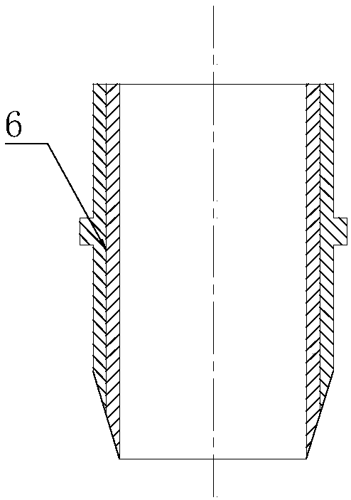
[0033] Specific implementation mode three: combination Figure 1-Figure 3 Describe this embodiment, the coring device for subgrade soil described in this embodiment, the section of the blade body 6 near the bottom end side wall is a wedge-shaped surface, and the cross-section of the wedge-shaped surface shrinks sequentially from top to bottom, and the bottom end of the blade body 6 is a blade portion , the edge angle of the blade portion is 17°, the effect of this structure is to insert the blade body 6 on the roadbed faster when using the blade body 6 for work, so as to increase work efficiency, and the other composition and connection relationship are the same as the specific embodiment one .


PUM

PropertyMeasurementUnit
angleaaaaaaaaaa
diameteraaaaaaaaaa
lengthaaaaaaaaaa

Abstract

The invention relates to a coring device for roadbed soil and a method for installing a moisture sensor by using the coring device. The object of the present invention is to solve the problem that thesoil compactness of a portion tested by a probe in the prior art often fails to meet the compactness requirement of the roadbed, so that the test accuracy of volumetric moisture content is affected,soil core sample is prone to loose in the process of lowering a moisture sensor with the soil core sample, the moisture sensor can be damaged easily in a layered compaction and backfilling process, and water can easily enter the moisture sensor during long-term monitoring. The coring device comprises a blade body, a confinement ring, a cushion block and a plurality of top wires; the outer side wall of a annular cylinder body is provided with a limiting protrusion of the confinement ring, wherein the confinement ring is an annular sleeve body, and the confinement ring is sleeved on the top endof the blade body; and the cushion block covers on the blade body and the confinement ring. The method comprises/includes: step 1, drilling and sampling; step 2, coring; step 3, inserting the moisturesensor; step 4, assembling a core sample; step 5, installing the core sample; step 6, backfilling the soil; step 7, sealing the hole. The coring device for roadbed soil and the method for installingmoisture sensor by using the coring device are used in the field of roadbed monitoring.

Description

technical field [0001] The invention relates to a coring device for roadbed soil and a method for installing a moisture sensor by using the coring device. The invention relates to monitoring the moisture content of roadbed soil. Background technique [0002] The moisture content of the roadbed has a great influence on the roadbed. In seasonally frozen soil areas, if the water content in the subgrade is too high, the road is prone to frost heave damage in winter. In spring, the ice in the road melts, and the excessive water in the subgrade cannot be discharged in time, resulting in insufficient bearing capacity of the subgrade, resulting in The pavement cracked. In the humid and rainy areas in the south, too high water content in the roadbed will also cause the bearing capacity of the roadbed to be too low. Therefore, monitoring the water content of the roadbed during the operation process and studying the influence of the water content on the roadbed are the hopes of road ...

Claims


Application Information

Patent Timeline
Patent Type & Authority Applications(China)
IPC IPC(8): G01N33/24
CPCG01N33/246
Inventor 陆许峰张锋冯德成王东升易军艳范铀凯李涛封征宇唐康为林波王冠夫
Owner HARBIN INST OF TECH
Why Eureka
Try Eureka