Display device and display panel

A display panel and display area technology, applied to static indicators, instruments, semiconductor devices, etc., can solve problems such as uneven display brightness

Inactive Publication Date: 2018-12-21
KUNSHAN GO VISIONOX OPTO ELECTRONICS CO LTD
View PDF5 Cites 35 Cited by
  • Summary
  • Abstract
  • Description
  • Claims
  • Application Information

AI Technical Summary

Problems solved by technology

[0004] However, the number of pixel units in the row where the installation hole is located is less than the number of pixel units in the row where the installation hole is not provided, and the load of the scanning line in the row where the installation hole is located is different from the load of the scanning line in the row where the installation hole is not provided, resulting in display The light and dark stripes in the area, that is, the problem of uneven brightness

Method used


Image

  • Display device and display panel
  • Display device and display panel
  • Display device and display panel

Examples


Embodiment Construction

[0051] In order to make the above objects, features and advantages of the present invention more comprehensible, specific embodiments of the present invention will be described in detail below in conjunction with the accompanying drawings.

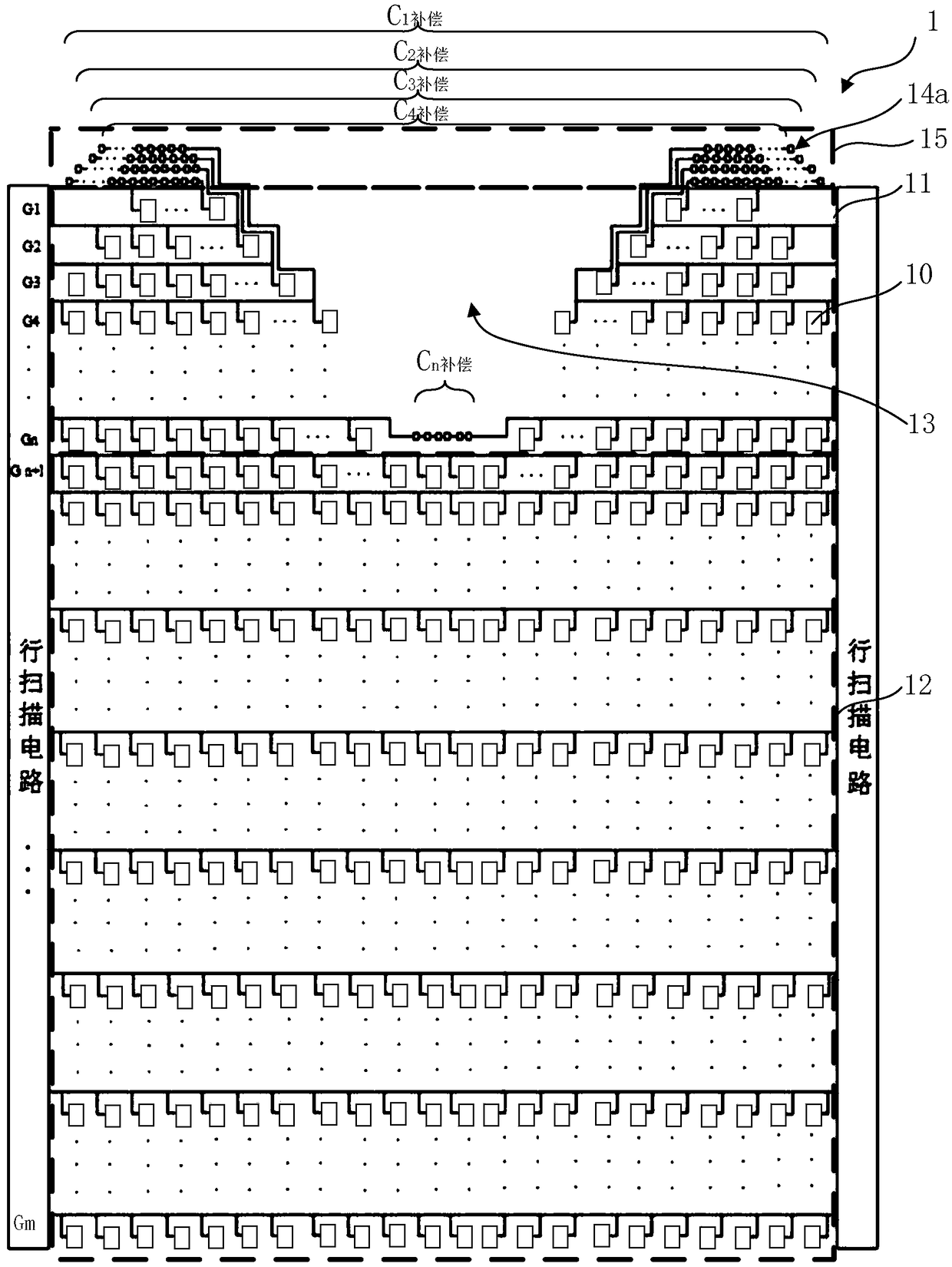
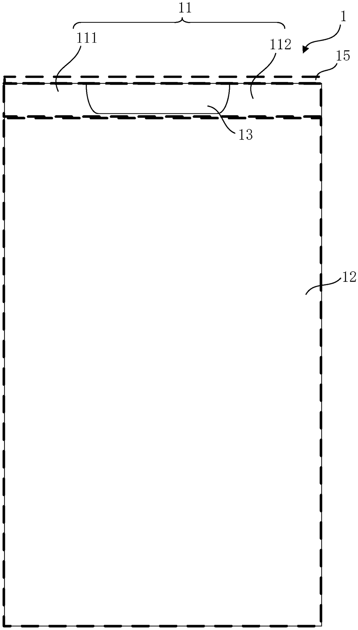
[0052] figure 1 is a schematic structural diagram of a display panel in an embodiment of the present invention. figure 2 yes figure 1 The partition diagram of each area of ​​the display panel is displayed in .

[0053] refer to figure 1 and figure 2 As shown, the display panel 1 includes: a first display area 11 and a second display area 12 adjacent up and down, and the first display area 11 includes: a plurality of pixel units 10 arranged in an array and n rows of scanning lines G 1 , G 2 …G n , each scan line G 1 , G 2 …G n Each row of pixel units 10 is correspondingly driven; the second display area 12 includes: a plurality of pixel units 10 arranged in an array and several rows of scanning lines G n+1 , G n+2 …G m , each ...


PUM


Abstract

The invention provides a display device and a display panel. A standard of carrying out capacitor compensation on each line of scan lines of a first display area with relatively few pixel units comprises the fact that a capacitor total load value of the line of scan lines adjacent to a second display area is equal to own capacitor load value of a line of scan lines in the second display area, andthe capacitor total load value of each line of scan lines close to the second display area and the capacitor total load value of each line of scan lines away from the second display area are graduallyreduced. The display device and the display panel have the advantages that through utilization of the feature that human eyes are insensitive to gradually varied brightness variation, mutation of thecapacitor total load value of each line of compensated scan lines in the first display area and at the border of the first display area and the second display area is eliminated, so the display is uniform; and through gradual variation of the capacitor total load values in the first display area, a setting area of compensation capacitors is reduced, reduction of the area of a frame area is facilitated, a narrow frame is realized, and a screen-to-body ratio is increased.

Description

technical field [0001] The present invention relates to the technical field of display devices, in particular to a display device and a display panel thereof. Background technique [0002] In recent years, display devices, especially display devices based on organic light emitting diodes (Organic Light Emitting Diode, OLED) have become popular new flat-panel display products at home and abroad. The OLED display panel has the characteristics of self-illumination, wide viewing angle, short response time, high luminous efficiency, wide color gamut, low operating voltage, thin panel, large size, flexible panel, and simple manufacturing process. cost potential. [0003] When the display panel is applied to a mobile terminal product, installation holes need to be opened in the display area to reserve hardware installation positions such as a front camera, an earpiece or a Home button on the mobile terminal device. [0004] However, the number of pixel units in the row where the ...

Claims


Application Information

Patent Timeline
Patent Type & Authority Applications(China)
IPC IPC(8): G02F1/1362G02F1/1333H01L27/32G09G3/36G09G3/3266
CPCG02F1/13338G02F1/136286G09G3/3266G09G3/3674H10K59/00H10K59/131G09G3/3225G09G2300/0426G09G2320/0223H10K59/1216G09G3/3648G09G2310/0221G09G2320/0233
Inventor 赵国华吴剑龙
Owner KUNSHAN GO VISIONOX OPTO ELECTRONICS CO LTD
Why Eureka
Try Eureka