Multi-Field-Circuit Coupling Simulation Method for Permanent Magnet Wind Turbine

A technology for wind turbines and analog calculations, applied in calculations, computer-aided design, electrical digital data processing, etc., can solve problems such as lack of exploration of multi-field correlation and multi-field coupling

Active Publication Date: 2018-12-21
INNER MONGOLIA UNIV OF TECH
View PDF5 Cites 8 Cited by
  • Summary
  • Abstract
  • Description
  • Claims
  • Application Information

AI Technical Summary

Problems solved by technology

[0006] At present, most researchers in the wind power industry either focus on the analysis of the heat dissipation characteristics of fluid-solid conjugate heat transfer, or focus on the energy analysis based on electromagnetic loss, or focus on the output characteristics analysis of field-circuit coupling, and lack of exploration of multi-field correlation and multi-field correlation. Calculation Method of Field Coupling's Influence on Output Characteristics

Method used


Image

  • Multi-Field-Circuit Coupling Simulation Method for Permanent Magnet Wind Turbine
  • Multi-Field-Circuit Coupling Simulation Method for Permanent Magnet Wind Turbine
  • Multi-Field-Circuit Coupling Simulation Method for Permanent Magnet Wind Turbine

Examples


Embodiment Construction

[0078] Below in conjunction with specific embodiment, further illustrate the present invention. It should be understood that these examples are only used to illustrate the present invention and are not intended to limit the scope of the present invention. In addition, it should be understood that after reading the teachings of the present invention, those skilled in the art can make various modifications or changes to the present invention, and these equivalent forms also fall within the scope defined by the appended claims of the present application.

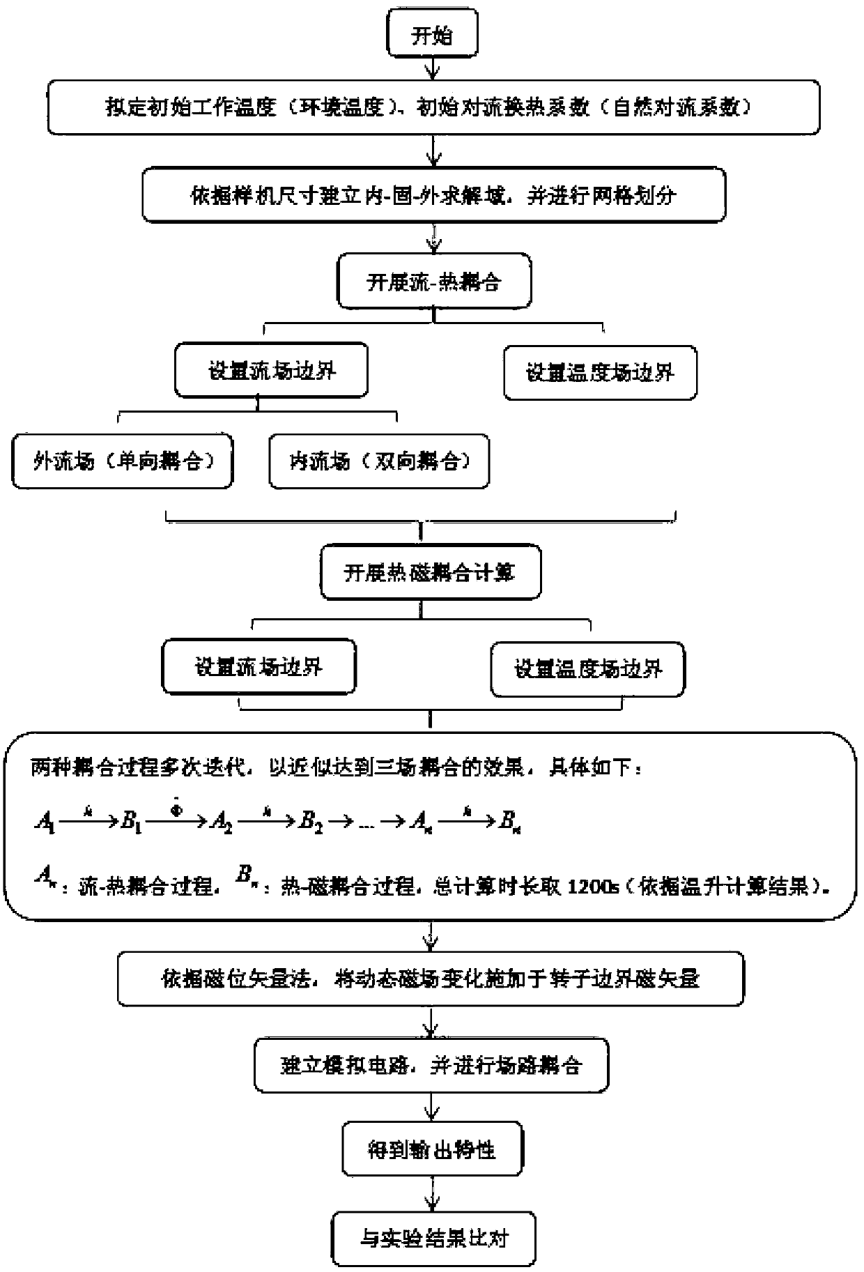
[0079] Such as figure 1 Shown is a schematic flow chart of the multi-field-way coupling numerical simulation calculation flow chart of the permanent magnet wind power generator described in the present invention, with the TL-500w generator as a prototype, the specific steps of the method shown in the figure are as follows:

[0080] (1) Considering the characteristics of the fluid-solid conjugate heat transfer problem to be sol...


PUM


Abstract

The invention relates to the technical field of a permanent magnet generator, in particular to a permanent magnet wind generator with multiple fields. Road coupling simulation method to establish theinner watershed-solid domain-outer watershed solving domain model, unstructured mesh partitioning; Applying material attributes according to the actual physical properties of each component; the initial constraint conditions of numerical simulation are collected, and the results are applied in the form of inlet conditions and rotating mechanical excitation. The initial boundary temperature and IHGinternal heat source are applied to compute and analyze the flow field and temperature field, and the flow is completed. The two-way exchange process of heat transfer, wall temperature and heat transfer coefficient on the solid contact surface realizes the generator flow. Thermal bi-directional coupling; The temperature distribution is applied to the electromagnetic field calculation, and the dynamic magnetic field variation is obtained by simulating the alternating magnetic field. The electromagnetic loss is returned to the heat source in the IHG. Numerical simulation results are obtained byrepeated iterations in the coupled flow field. The invention has the advantages of accurate and intuitive results, and can make up the limitation of the existing experimental means.

Description

technical field [0001] The invention relates to the technical field of permanent magnet generators, in particular to a multi-field-circuit coupling simulation calculation method for permanent magnet wind power generators. Background technique [0002] At present, due to the increasing shortage of traditional fossil fuels and the impact of the international energy crisis environment, renewable energy has become the focus of energy practitioners in various countries It has great potential to replace traditional power generation methods and change the energy pattern. Wind power has gradually driven the operation of modern industries and entered ordinary households. With the development of wind power technology, wind energy will eventually be universally developed and expanded. [0003] Although wind power generation technology has been developed for nearly a century, with the continuous expansion of the application and operating range of wind power generators, the performance ...

Claims


Application Information

Patent Timeline
Patent Type & Authority Applications(China)
IPC IPC(8): G06F17/50
CPCG06F2119/08G06F30/23G06F30/20
Inventor 温彩凤张建勋汪建文刘珍张立茹东雪青高志鹰曹阳
Owner INNER MONGOLIA UNIV OF TECH
Why Eureka
Try Eureka