
Variable pinhole collimator and radiographic imaging device using same

一种准直器、针孔的技术,应用在应用、辐射诊断用隔膜、辐射/粒子处理等方向,能够解决图像灵敏度降低、驱动复杂化、位置和大小劣化等问题,达到降低制造成本、简化结构、减小大小的效果

Active Publication Date: 2018-12-21
ARALE LAB CO LTD
View PDF13 Cites 5 Cited by
  • Summary
  • Abstract
  • Description
  • Claims
  • Application Information

AI Technical Summary

Problems solved by technology

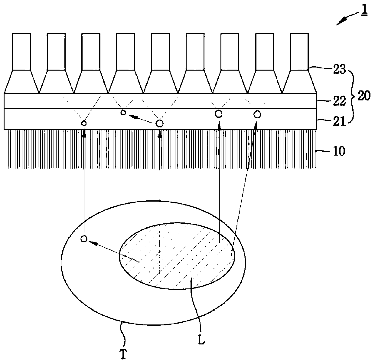
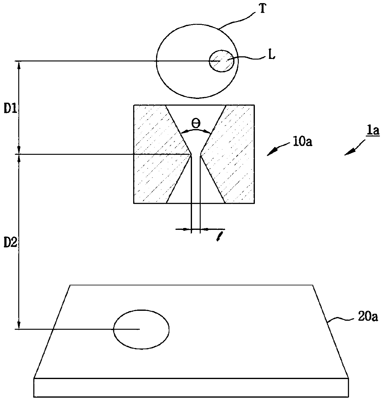
[0015] However, as far as the conventional pinhole collimator (10a) is concerned, since the acceptance angle (θ) and the hole diameter (1) are fixed, there are the following problems: the resolution and sensitivity vary according to the Region Of Interest (ROI ) is degraded by the location and size of
[0020] However, Figure 4 The problem with the method shown in (b) is that the patient should be injected more Radioactive material for increased sensitivity
[0024] However, the problem with the above pinhole collimator is that since it is configured so that multiple apertures are laminated to adjust the acceptance angle or direction of the pinhole, multiple plates should be used to form one aperture, and thus , the number of laminated plates increases to the number of apertures forming the pinhole collimator multiplied by the number of plates forming an aperture, thereby increasing the thickness of the pinhole collimator
[0025] In addition, as for the region where the orifice is narrowed (especially the hole diameter portion), for example, even if one orifice constitutes the hole diameter, it is formed by overlapping a plurality of sheets by laminating a plurality of sheets constituting one orifice. Hole diameter, which in turn limits the formation of pinholes with higher precision
[0026] Furthermore, for each aperture, a drive unit for adjusting each aperture is required, which complicates the drive and increases the overall size and weight of the collimator
When the drive unit is applied to a single photon emission computed tomography apparatus, the weight of the gantry increases, which is a limiting factor for the implementation of the gantry rotation mechanism

Method used


Image

  • Variable pinhole collimator and radiographic imaging device using same
  • Variable pinhole collimator and radiographic imaging device using same
  • Variable pinhole collimator and radiographic imaging device using same

Examples


Embodiment Construction

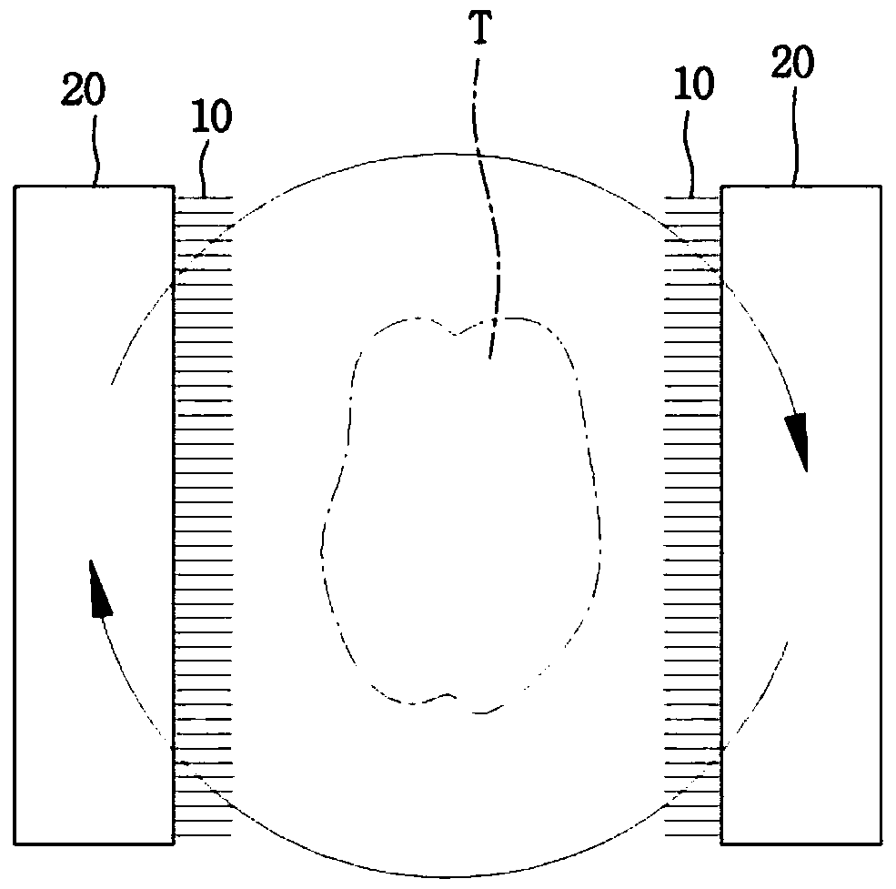
[0072] The present invention relates to a variable pinhole collimator and a radiographic imaging device using the same. The variable pinhole collimator according to the present invention includes: a plurality of pinhole plates in each of the plate surfaces provided with a plurality of pinholes at positions of the same radius from the rotation axis in the circumferential direction and having sizes different from each other A hole-forming hole is provided in each plate surface of the plurality of pinhole plates provided with a plurality of rotation operation holes around a rotation axis in a circumferential direction, and the plurality of pinhole plates are arranged so that in an incident direction of radiation performing lamination; and a drive module configured to be sequentially inserted into the rotation operation holes of the plurality of pinhole plates in the incident direction to rotate the plurality of pinhole plates around a rotation axis, and configured to cause the plu...


PUM


Abstract

The present invention relates to a variable pinhole collimator and a radiographic imaging device using the same. The variable pinhole collimator according to the present invention comprises a plurality of pinhole plates in each of which a plurality of pinhole formation holes having mutually different sizes are formed along a circumferential direction and a plurality of rotation operation holes areformed around a rotational axis and along the circumferential direction, and which are stacked in a direction in which radiation is incident; and a driving module drawn into the plurality of rotationoperation holes in the plurality of pinhole plates sequentially in the incident direction, for rotating the plurality of pinhole plates about the rotational axis, wherein the plurality of pinhole plates are rotated, thereby forming a pinhole in an overlapping area. Accordingly, various pinhole shapes can be achieved since it is possible to change a pinhole-configuring parameter of the variable pinhole collimator.

Description

technical field [0001] The present invention generally relates to a variable pinhole collimator and a radiographic imaging apparatus using the same. More particularly, the present invention relates to a variable pinhole collimator and a radiographic imaging device using the same, which determine, for example, a gamma camera or A radiation passing area or a direction of radiation in a radiographic imaging device of a single photon emission computed tomography (Single Photon Emission Computed Tomography, SPECT) device. Background technique [0002] A radiographic imaging device is a device that acquires images using radioactive isotopes, and is one of devices widely used in the fields of nuclear medicine diagnostics and nondestructive inspection. [0003] Unlike other diagnostic devices such as magnetic resonance imaging (MRI) or ultrasonic diagnostic devices that provide structural information of the human body, radiographic imaging devices for nuclear medicine diagnostics s...

Claims


Application Information

Patent Timeline
Patent Type & Authority Applications(China)
IPC IPC(8): A61B6/00A61B6/03
CPCA61B6/00A61B6/03G21K1/046A61B6/037A61B6/4291A61B6/06A61B6/12A61B6/4258A61B6/54
Inventor 李学宰李起成车慧美
Owner ARALE LAB CO LTD
Learn More