Method and filling device for filling a transport container with a fluid
A transport container, fluid-filled technology that is used in transport and packaging, liquid distribution, transport or transfer devices, chemical instruments and methods, and can solve problems such as intensive and complex costs
- Summary
- Abstract
- Description
- Claims
- Application Information
AI Technical Summary
Problems solved by technology
Method used
Image
Examples
example 1
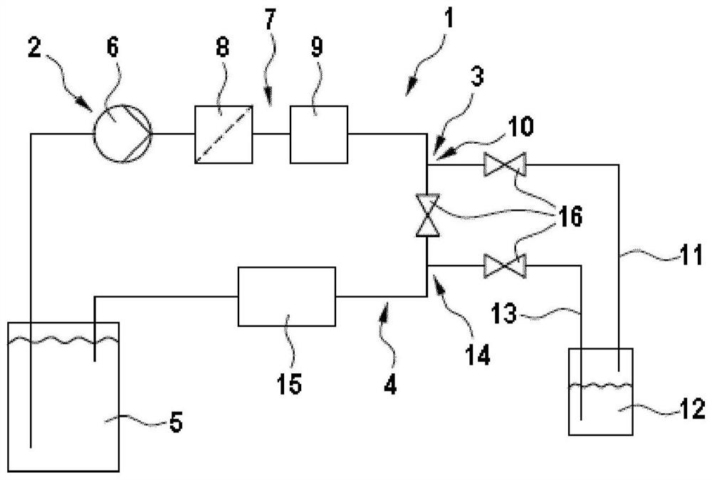
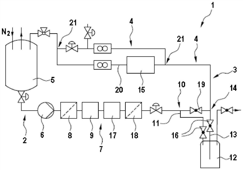
[0049] The mixed fluid is conveyed by means of gas pressure through purified nitrogen into the storage container 5 of the filling device, which substantially corresponds to figure 2 Filling device shown in . The nitrogen used for delivery had previously been filtered through a gas filter. according to figure 1 , the storage vessel 5 was connected to a pump 6 (Levitronix), a membrane degassing unit 9 and two PTFE filters 8, 18 (Entegris) with pore sizes of 0.1 μm and 0.05 μm, respectively. The purification process according to the invention is carried out in such a way that the fluid is initially circulated in the optical particle counter through the pump 6, the filter device 7 and the pollution measurement device 15, the measured key pollution indicators are respectively compared with the desired or pre-defined target parameters for comparison. The fluid (respectively ink or just solvent) returns to the storage container 5 after passing through the contamination measuring ...
example 2
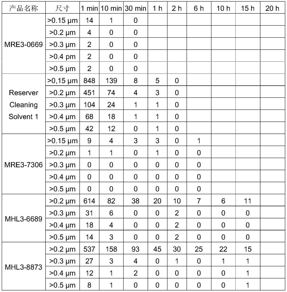
[0058] The filling process begins as soon as the corresponding fluid according to example 1 is present in the purge circuit in a purge manner. Here, the transport container 12 is integrated into the purification circuit 1 . The fluid quantity taken from the transport container 12 thus flows back into the cleaning circuit via the valve 16 and the connection 14 . A throughflow and contamination measuring device 15 is located in the return line to the storage container 5 , via which the overall dissolved gas content, in particular the oxygen content, can be detected. The shipping container 12 is flushed with the already cleaned fluid until the target parameters are achieved in the return flow from the shipping container 12 . As an example, a number of 150 ml bottles (Merck decontaminated glass bottles, decontaminated) were used as shipping containers 12 and filled with "Reserver Cleaning Solvent" fluid. Here, the bottles are incorporated into the purification circuit 1 until th...
example 3
[0062] The filling process begins as soon as the desired fluid according to example 1 is present in the purge circuit in a purge manner. In this example, the filling of the transport container 12 configured as an ink cartridge 30 is described. To this end, the filling device includes the additional function of flushing the transport container 12 , ie flushing the transport container 12 by alternately filling and emptying it with already purified fluid. This alternating operation is repeated a number of times until the desired pollution concentration is achieved and is below a predefined threshold for key pollution indicators. To this end, during emptying of the transport container 12, the container return line 13 is connected to the fluid line portion 3 and subsequently to the contamination measuring device 15 in order to establish key contamination indicators. After passing through the contamination measuring device 15 the fluid returns to the storage container 5 and is agai...
PUM
 Abstract
Description
Claims
Application Information
 - R&D
- Intellectual Property
- Life Sciences
- Materials
- Tech Scout
- Unparalleled Data Quality
- Higher Quality Content
- 60% Fewer Hallucinations
Browse by: Latest US Patents, China's latest patents, Technical Efficacy Thesaurus, Application Domain, Technology Topic, Popular Technical Reports.
© 2025 PatSnap. All rights reserved.Legal|Privacy policy|Modern Slavery Act Transparency Statement|Sitemap|About US| Contact US: help@patsnap.com


