
Set for dispensing liquefied gas

A liquefied gas, kit technology, applied in fluid handling accessories, gas handling/storage purposes, gas/liquid distribution and storage, etc., can solve complex, dangerous and other problems

Active Publication Date: 2018-12-21
CRYOSTAR
View PDF7 Cites 7 Cited by
  • Summary
  • Abstract
  • Description
  • Claims
  • Application Information

AI Technical Summary

Problems solved by technology

[0011] - Extraction of the pump from the container, in particular for repair or maintenance of this pump, requires separation of the sealing assembly from the regulating system prior to removal of the pump and removal of the pump from the container, which can be complicated or dangerous depending on the gas dispensed ;as well as

Method used


Image

  • Set for dispensing liquefied gas
  • Set for dispensing liquefied gas
  • Set for dispensing liquefied gas

Examples


Embodiment Construction

[0037] Several installations and embodiments of the invention are now described in detail, without in any way limiting the scope of the claims. In particular, the application of filling stations dedicated to road vehicles (eg trucks) is described, but other applications are also embodied by the claims, with the same embodiment features or embodiments adapted to gas and / or to the application feature.

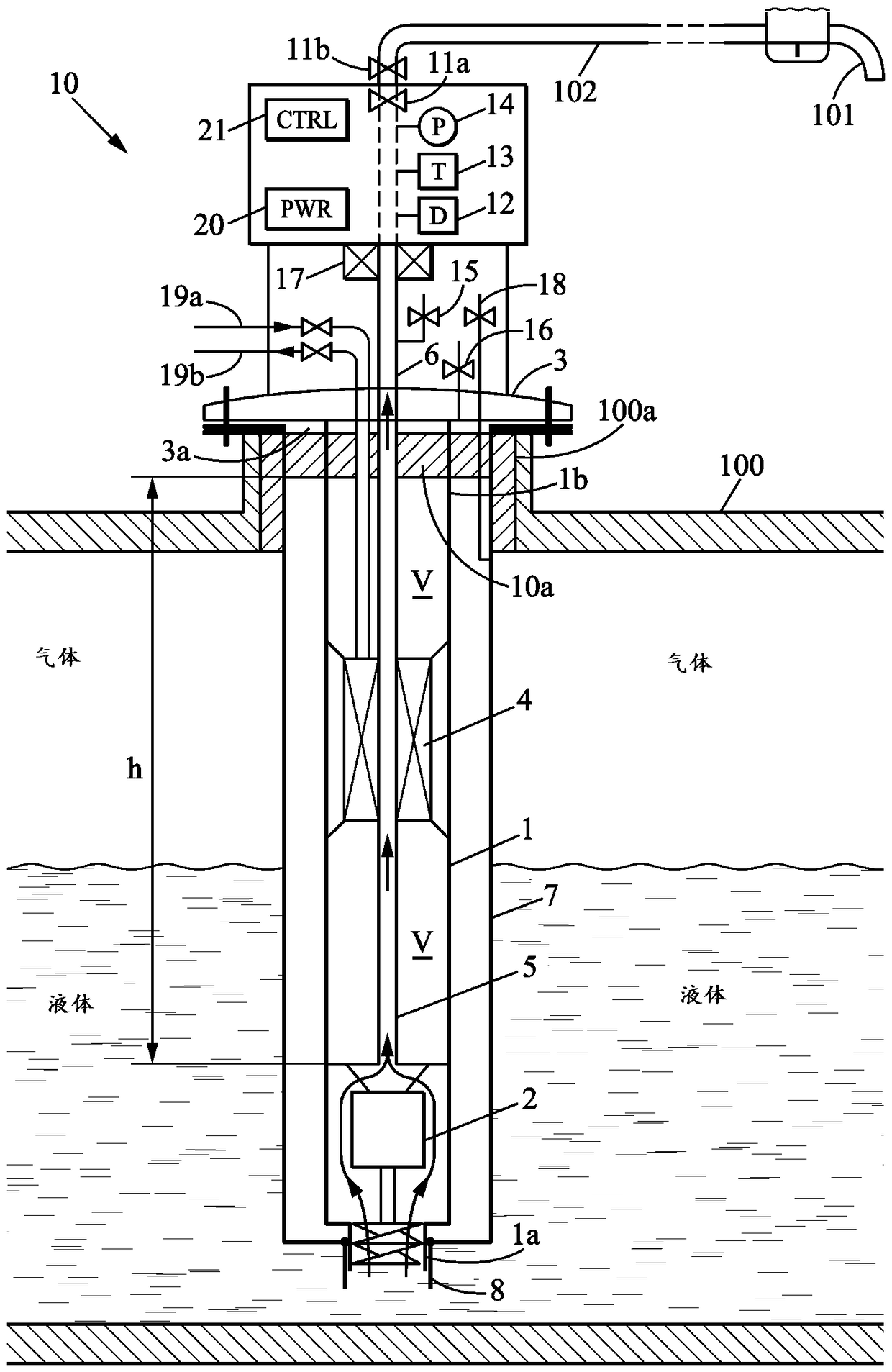
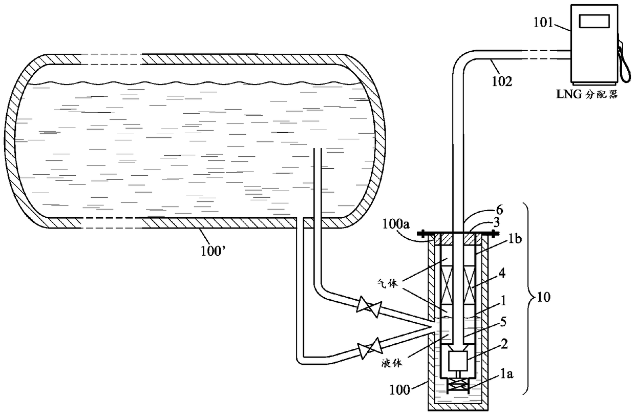
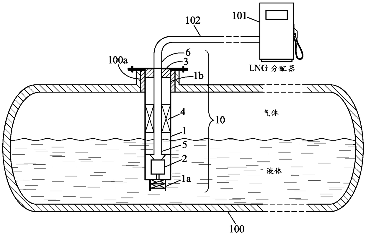
[0038] exist Figure 1a and 1b In , the following reference numerals have the meanings now listed:

[0039] 100 Containers for liquefied motor fuel gas

[0040] 100a Orifice in wall of container 100

[0041] 100' storage tank

[0042]101 Liquefied gas distributor

[0043] 102 Pipe for supplying liquefied gas to distributor 101

[0044] 10 Kit for dispensing liquefied motor fuel gas mounted in container 100

[0045] 1 Support structure

[0046] 1a Suction end of support structure 1

[0047] 1b Discharge end of support structure 1

[0048] 2 pumps

[0049] 3 Removable se...


PUM


Abstract

A set (10) for dispensing liquefied gas from a vessel (100) comprises a supporting structure (1), a pump (2) and a conditioning system (4). The supporting structure is designed for maintaining both the pump and the conditioning system inside the vessel when the set is in an operation condition for dispensing a flow of liquefied gas. The set allows easy handling, simple fitting to the vessel and easy removal from the vessel because a main part of said set can be handled as a one-block element.

Description

technical field [0001] The invention relates to a kit for dispensing a liquefied gas flow from a container containing gas in liquid phase. Background technique [0002] Kits for dispensing liquefied gas from storage containers typically include a pump and a liquefied gas conditioning system. In known kits of this type, the pump can be designed to be submerged in the liquefied gas inside the container, and the regulating system is arranged outside the container, between the container and the distributor of the liquefied gas. Thus, known kits for dispensing a liquefied gas flow from a container containing a gas in liquid phase comprise respectively: [0003] - a support structure that connects the suction and discharge ends and that is adapted to fit tightly to the container so that the suction end is submerged in the liquefied gas inside the container, while the discharge end is located at the outer surface of the container; [0004] - a pump to be held by a supporting stru...

Claims


Application Information

Patent Timeline
Patent Type & Authority Applications(China)
IPC IPC(8): F17C9/00
CPCF17C6/00F17C2201/0109F17C2201/035F17C2201/054F17C2205/0332F17C2221/011F17C2221/012F17C2221/014F17C2221/017F17C2221/033F17C2221/035F17C2223/0153F17C2223/0161F17C2223/033F17C2223/043F17C2223/047F17C2225/0153F17C2225/0161F17C2225/033F17C2225/035F17C2227/015F17C2227/0178F17C2227/0304F17C2227/0309F17C2227/0341F17C2227/0379F17C2227/039F17C2250/032F17C2250/043F17C2250/0439F17C2250/0443F17C2250/0491F17C2250/0626F17C2250/0631F17C2250/0636F17C2260/035F17C2265/061F17C2265/065F17C2265/066F17C2270/0105F17C2270/0139F17C2270/0168F17C2270/0171F17C2270/0173F17C2270/0194F17C2270/0197F17C9/00Y02E60/32
Inventor S.乌里
Owner CRYOSTAR
Learn More