Needle circling means and winding machine
A component and needle tube technology, which is applied in the field of straight-wound winding machines, can solve the problems of prolonged armature manufacturing time, inability to circulate insulators, and limited range of changes, so as to improve the versatility, the arrangement accuracy, and the movement. Responsiveness-enhancing effect
- Summary
- Abstract
- Description
- Claims
- Application Information
AI Technical Summary
Problems solved by technology
Method used
Image

Examples
Embodiment 1
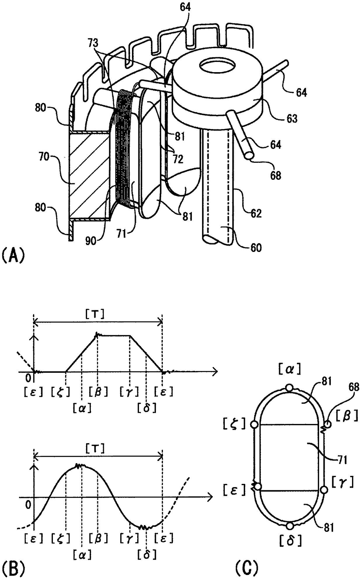
[0116] First refer to figure 2 , to illustrate the state of winding the coil wires on the magnetic pole teeth 71 of the stator core 70 with a direct-wound winding machine, and the overshoot that easily occurs when the traditional winding machine winds at high speed. To make figure 2 (A) is easier to understand, and a part of the stator core and the tip of the inner cylinder 60 for guiding the coil wire are described in a perspective view. In addition, the imaginary line of the inner cylinder 60 is shown by the dashed-dotted line. The stator core 70 is composed of a plurality of laminated thin plates, and insulators 80, 80 are installed on the upper and lower end surfaces thereof.
[0117] The stator core 70 is penetrated by slots 73 through which the magnetic pole teeth 71 protruding inwardly formed in the stator core are interposed and the coil wires are wound. The inner side of the magnetic pole teeth 71 is formed as a flange portion 72 protruding in the circumferential d...
Embodiment 2
[0141] Then refer to Figure 6 , illustrating that the needle circulation assembly 2 of the circulation track is controlled by the circulation track control assembly when corresponding to insulators of different shapes. Figure 6 Figure (A) shows an example of the cyclic motion of an insulator suitable for an upstanding wall 82 in the shape of a narrow hexagon above which the upper side is parallel to the lower side and connected to a vertical line by a hypotenuse.
[0142] Specifically, in order to correspond to only the length of the vertical line (refer to Figure 6 (A) figure) the insulator which has the vertical wall 82 of a substantially trapezoidal shape by extending the length a, and changes the example of the circulating track. Figure 6 The (B) diagram shows the synthesis to Figure 6 (A) Diagram of the orbital offset of the pendulum motion of the tip of the needle. Figure 6 The (C) diagram shows the synthesis to Figure 6 (A) Diagram of the trajectory of the of...
Embodiment 3
[0147] In Example 3, refer to Figure 7 , illustrating that the position of the top of the circulating track controlled by the circulating track control component is changed toward the starting end side of the swing movement. Figure 7 The demand line shown in (A) is the state where the position of the vertex before the change is still positioned at the center of the magnetic pole teeth, and the solid line shows that the position α of the vertex after the change is moved closer to the center of the magnetic pole teeth. The state of the originating side. In addition, the position of the vertex before the change of the cyclic orbit is shown by a chain circle.
[0148] Figure 7 The dotted line shown in (B) is the position change of the swing motion before the top position is changed, and the solid line is the position change of the swing motion when the top position α moves from the center of the magnetic pole teeth to the starting end side of the swing motion. Figure 7 The ...
PUM
 Abstract
Description
Claims
Application Information
 - R&D
- Intellectual Property
- Life Sciences
- Materials
- Tech Scout
- Unparalleled Data Quality
- Higher Quality Content
- 60% Fewer Hallucinations
Browse by: Latest US Patents, China's latest patents, Technical Efficacy Thesaurus, Application Domain, Technology Topic, Popular Technical Reports.
© 2025 PatSnap. All rights reserved.Legal|Privacy policy|Modern Slavery Act Transparency Statement|Sitemap|About US| Contact US: help@patsnap.com