Needle loop assembly and winding machine

A technology of components and needle tubes, applied in the field of direct winding winding machines, can solve the problems of prolonged armature manufacturing time, limited range of changes, inability to circulate insulators, etc., to improve versatility, improve arrangement accuracy, and move Effect of Responsive Improvement

Inactive Publication Date: 2020-03-27
ETEC
View PDF7 Cites 0 Cited by
  • Summary
  • Abstract
  • Description
  • Claims
  • Application Information

AI Technical Summary

Problems solved by technology

Therefore, a large cam mechanism is necessary, which makes it difficult to move at a high speed and cannot be wound at a high speed. The manufacturing time of the armature is prolonged and the production efficiency is low.
In addition, in this technology, the orbit of the needle tube can be changed in a limited range, and when the insulator is changed, there will be a problem that the orbit that is most suitable for the changed insulator cannot be circulated.

Method used


Image

  • Needle loop assembly and winding machine
  • Needle loop assembly and winding machine
  • Needle loop assembly and winding machine

Examples


Embodiment 1

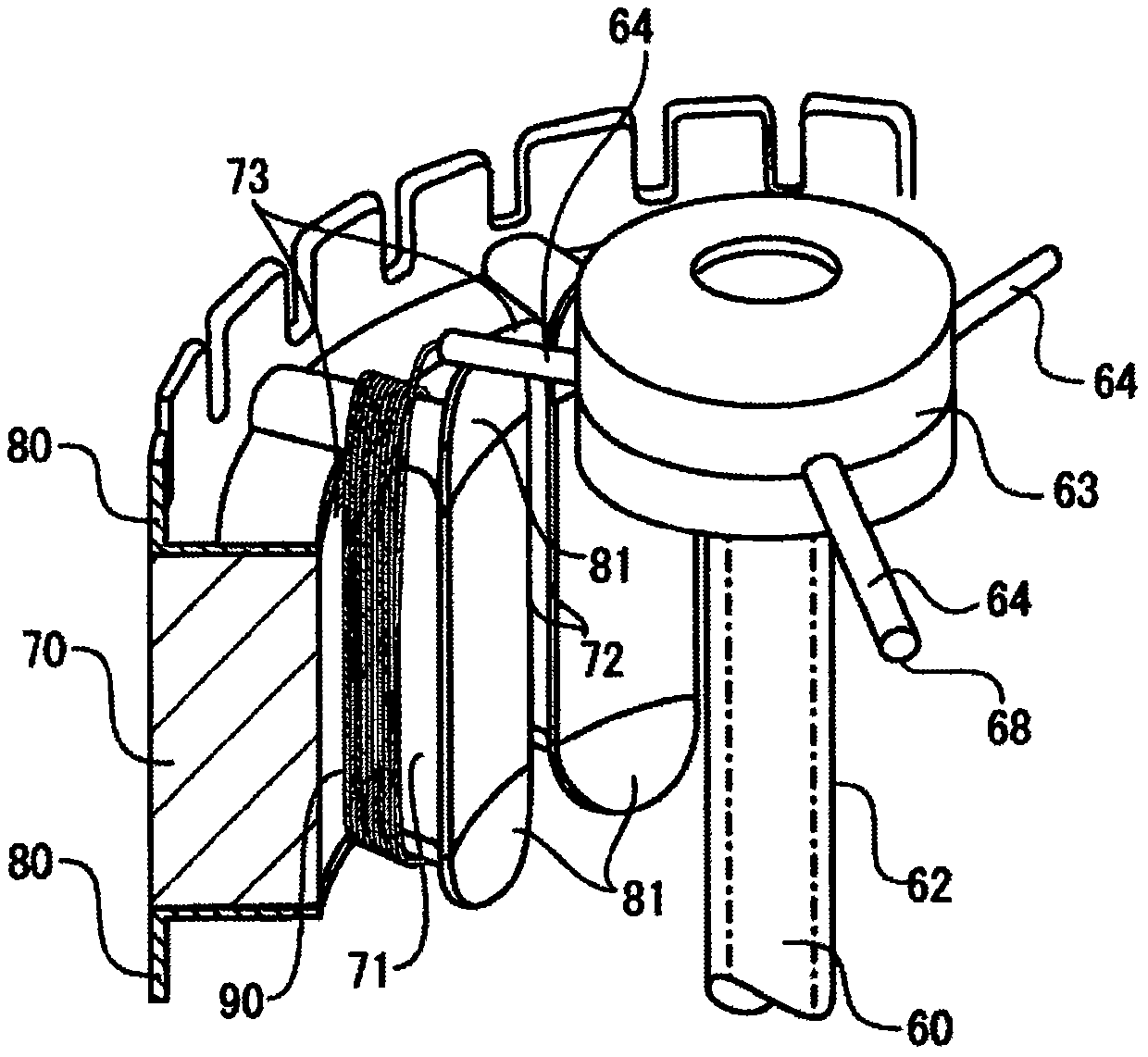
[0116] First refer to figure 2 , Figure 2A ~ Figure 2C , to illustrate the state of winding the coil wires on the magnetic pole teeth 71 of the stator core 70 with a direct-wound winding machine, and the overshoot that easily occurs when the traditional winding machine winds at high speed. To make figure 2 To make it easier to understand, a part of the stator core and the tip of the inner tube 60 for guiding the coil wire will be described in a perspective view. In addition, the imaginary line of the inner cylinder 60 is shown by the dotted line. The stator core 70 is composed of a plurality of laminated thin plates, and insulators 80, 80 are installed on the upper and lower end surfaces thereof.

[0117] The stator core 70 is penetrated by slots 73 through which the magnetic pole teeth 71 protruding inwardly formed in the stator core are interposed and the coil wires are wound. The inner side of the magnetic pole teeth 71 is formed as a flange portion 72 protruding in ...

Embodiment 2

[0141] Next, with reference to FIG. 6 , the needle circulation assembly 2 that controls the circulation track through the circulation track control assembly when corresponding to insulators of different shapes is illustrated. Figure 6A Shown is an example of cyclical motion suitable for an insulator with upper and lower sides parallel and joined by a hypotenuse to a vertical line, with an upstanding wall 82 of narrow hexagonal shape above.

[0142] Specifically, in order to correspond to only the length of the vertical line (refer to Figure 6A ) An example in which the length a of the insulator having the vertical wall 82 of a substantially trapezoidal shape is extended, and the circulating track is changed. Figure 6B The figure shows the synthesis to Figure 6A The track is offset by the oscillating motion of the tip of the needle tube. Figure 6C shows the synthesis to Figure 6A The track offsets the linear motion of the tip of the needle tube.

[0143] Then, if the ...

Embodiment 3

[0147] In Example 3, refer to Figure 7A ~ Figure 7C , illustrating that the position of the top of the circulating track controlled by the circulating track control component is changed toward the starting end side of the swing movement. Figure 7A The demand line shown is the state where the position of the vertex before the change is still positioned at the center of the magnetic pole teeth, and the solid line shows the state where the position α of the vertex after the change is close to the starting end side of the swing motion from the center of the magnetic pole teeth . In addition, the position of the vertex before the change of the cyclic orbit is shown by a chain circle.

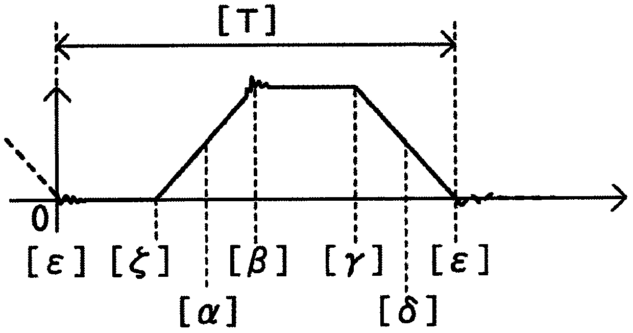
[0148] Figure 7B The dotted line shown is the position change of the swing motion before the vertex position is changed, and the solid line is the position change of the swing motion when the vertex position α moves from the center of the magnetic pole teeth to the start end side of the swing mo...


PUM


Abstract

[Problem] To provide a needle circling means and a series winding-type winding machine that comprises said needle circling means, wherein winding can be performed at a high speed, a coil wire that has been wound has high alignment accuracy, and when an insulator of a different shape is used, the trajectory of a needle can be changed without rearranging the winding machine. [Solution] This servo motor for linear motion and this servo motor for oscillating motion are made to rotate only in one direction, and each servo motor is fixed to a base in an independent manner. Additionally, a circling trajectory control means controls the speed of the rotational motion of each servo motor and allows the circling trajectory of a tip of a needle to be changed.

Description

technical field [0001] The present invention relates to a winding machine for winding a coil wire on a magnetic pole tooth by direct winding from the inner diameter side of a stator core having a circular cross-section having a plurality of magnetic pole teeth inside. Specifically, it relates to a needle tube circulation assembly that drives the tip of a thin cylinder (hereinafter referred to as "needle tube") that sends out coil wires to move in an elliptical orbit around the magnetic pole teeth, and a needle tube circulation assembly that includes the needle tube circulation assembly. thread machine. In detail, it relates to a needle tube circulation assembly that can be wound at high speed, and the wound coil wires have high alignment accuracy. When using insulators of different shapes, it is not necessary to replace the combination of the winding machine, and the needle tube track can also be changed. And a direct winding winding machine including the needle tube circulat...

Claims


Application Information

Patent Timeline
Patent Type & Authority Patents(China)
IPC IPC(8): H02K15/095
CPCH02K15/095
Inventor 细野圣二小岛昌男
Owner ETEC
Why Eureka
Try Eureka