Supercharge Your Innovation With Domain-Expert AI Agents!

Efficiency grinding equipment for coating processing

A high-efficiency, coating technology, applied in solid separation, sieves, grids, etc., can solve the problems of high labor intensity of operators, uneven grinding quality, low work efficiency, etc., to improve grinding quality, reduce labor intensity, improve quality effect

Inactive Publication Date: 2018-12-25
周兆平
View PDF1 Cites 0 Cited by
  • Summary
  • Abstract
  • Description
  • Claims
  • Application Information

AI Technical Summary

Problems solved by technology

[0003] The purpose of the present invention is to overcome the problems of low grinding efficiency, uneven grinding quality, high labor intensity and low work efficiency of the existing paint grinding equipment, and provide a kind of equipment with reasonable structure design, high work efficiency, high grinding efficiency and easy operation. High-efficiency grinding equipment for coating processing with low labor intensity and good grinding quality uniformity

Method used


Image

  • Efficiency grinding equipment for coating processing
  • Efficiency grinding equipment for coating processing
  • Efficiency grinding equipment for coating processing

Examples


Embodiment 1

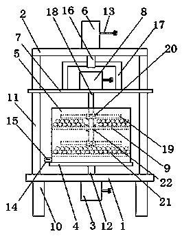
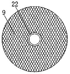
[0017] as attached figure 1 and 2 As shown, a high-efficiency grinding equipment for coating processing includes a base 1, a fixed plate 2, a motor one 3, a bearing plate 4, a grinding barrel 5, a cylinder 6, an adjustment plate 7, a motor two 8 and a filter plate 9, and is characterized in that : the base 1 is arranged on the support 10, and the base 1 is provided with a column 11, the fixed plate 2 is arranged on the column 11, the motor-3 is arranged on the base 1, and the motor-1 3 is provided with a power cord 13 and a transmission shaft 12, the bearing plate 4 is arranged on the transmission shaft 12, the grinding barrel 5 is arranged on the bearing plate 4, and a discharge plate is arranged at the bottom of the grinding barrel 5 Pipe 14, the cylinder 6 is arranged on the fixed plate 2, and the power cord 13 and the piston rod 16 are arranged on the cylinder 6, the adjustment plate 7 is arranged on the column 11, and the adjustment plate 7 is passed through the connecti...

Embodiment 2

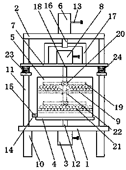
[0023] as attached image 3 As shown, a high-efficiency grinding equipment for coating processing includes a base 1, a fixed plate 2, a motor one 3, a bearing plate 4, a grinding barrel 5, a cylinder 6, an adjustment plate 7, a motor two 8 and a filter plate 9, and is characterized in that : the base 1 is arranged on the support 10, and the base 1 is provided with a column 11, the fixed plate 2 is arranged on the column 11, the motor-3 is arranged on the base 1, and the motor-1 3 is provided with a power cord 13 and a transmission shaft 12, the bearing plate 4 is arranged on the transmission shaft 12, the grinding barrel 5 is arranged on the bearing plate 4, and a discharge plate is arranged at the bottom of the grinding barrel 5 Pipe 14, the cylinder 6 is arranged on the fixed plate 2, and the power cord 13 and the piston rod 16 are arranged on the cylinder 6, the adjustment plate 7 is arranged on the column 11, and the adjustment plate 7 is passed through the connecting rod ...


PUM


Abstract

The invention discloses efficiency grinding equipment for coating processing. The efficiency grinding equipment comprises a base, a fixing plate, a first motor, a load bearing plate, a grinding barrel, an air cylinder, an adjusting plate, a second motor and a filtering plate, and is characterized in that the base is arranged at a bracket; the fixing plate is arranged at stand columns; the first motor is arranged at the base; the load bearing plate is arranged at a first transmission shaft; the grinding barrel is arranged on the load bearing plate; the air cylinder is arranged at the fixing plate; the adjusting plate is arranged on the stand columns; and the second motor is arranged on the adjusting plate. The adjusting plate is arranged to be of a structure capable of rising or lowering along the stand columns. The adjusting plate is lifted or lowered along the stand columns under action of the air cylinder and a piston rod to drive the second motor and a second transmission shaft to rise or lower, and therefore a stirring rod at the second transmission shaft can stir coating and grinding balls in the grinding barrel, and the coating grinding efficiency can be improved.

Description

technical field [0001] The invention relates to the technical field of paint processing, in particular to high-efficiency grinding equipment for paint processing. Background technique [0002] In the processing of coatings, the fineness and adhesion of coatings are important indicators of coatings. In order to improve the fineness and adhesion of coatings, it is necessary to grind the coatings. During the grinding process of coatings, a large amount of Heat, if the heat is not absorbed or transferred in time, the high temperature generated by the high heat will not only cause damage to the paint grinding equipment, but also reduce the quality and performance of the paint. At the same time, the existing paint equipment also has the problem of uneven paint grinding quality . For example, the patent application number 201510966261.3 discloses a high-efficiency paint grinding machine, which solves the problem of low paint grinding efficiency, but has the problem of uneven paint...

Claims


Application Information

Patent Timeline
IPC IPC(8): B02C17/16B02C17/10B02C17/18B02C23/16B07B1/46
CPCB02C17/16B02C17/10B02C17/18B02C23/16B07B1/4609B07B2201/04
Inventor 周兆平张强汪永生
Owner 周兆平
Features
  • R&D
  • Intellectual Property
  • Life Sciences
  • Materials
  • Tech Scout
  • Unparalleled Data Quality
  • Higher Quality Content
  • 60% Fewer Hallucinations
Learn More