
Battery liquid injecting hole cleaning method and cleaning device

A technology for cleaning devices and liquid injection holes, which is applied in the direction of cleaning methods and appliances, battery pack parts, chemical instruments and methods, etc. It can solve problems such as residual electrolyte, incomplete cleaning, and affecting the welding quality of sealing nails. The effect of safe and reliable operation and simple operation

Inactive Publication Date: 2018-12-25
WUHAN YIFI LASER EQUIP CO LTD
View PDF5 Cites 0 Cited by
  • Summary
  • Abstract
  • Description
  • Claims
  • Application Information

AI Technical Summary

Problems solved by technology

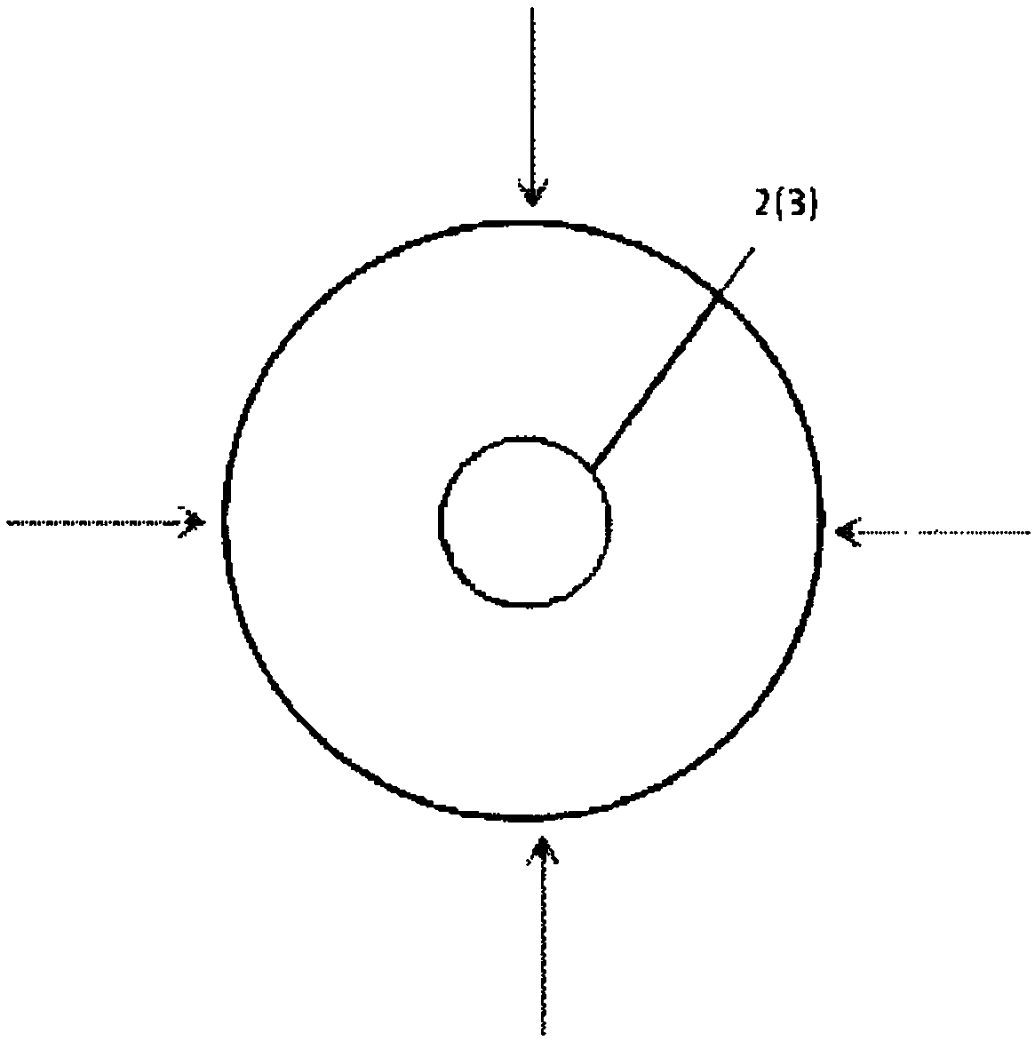
[0004] In the existing production process, the single battery is generally inserted into a sealing nail (such as a rubber nail) immediately after the electrolyte is injected, and then the residual electrolyte in the liquid injection hole and the surrounding area is wiped by physical methods, and then the marking machine is used to progressively 90-degree direction sequential filling marking cleaning (such as figure 2 As shown), although the electrolyte can be cleaned and removed by using this cleaning track, but the cleaning is not thorough in this way, and the electrolyte will still remain, which will still affect the welding quality of the sealing nail 3

Method used


Image

  • Battery liquid injecting hole cleaning method and cleaning device
  • Battery liquid injecting hole cleaning method and cleaning device
  • Battery liquid injecting hole cleaning method and cleaning device

Examples


Embodiment 1

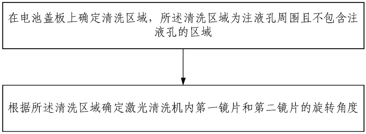
[0033] image 3 A preferred embodiment of the liquid injection hole 2 cleaning method on the battery of the present invention is shown, as image 3 As shown, the cleaning method includes: determining the cleaning area on the battery cover plate 1, the cleaning area is the area around the liquid injection hole 2 and not including the liquid injection hole 2; according to the cleaning area, the first lens 10 and the The angle of rotation of the second eyeglass 11; the first eyeglass 10 is inclined to the lower right, and the second eyeglass 11 is inclined to the upper right; the first eyeglass 10 is opposite to the laser head of the laser cleaning machine 7, and is positioned on the upper right of the second eyeglass 11 side; laser cleaning machine 7 also includes two motors; the motors are respectively connected with the first lens 10 and the second lens 11, and are respectively used to drive the first lens 10 and the second lens 11 to rotate.

[0034] Specifically, after the ...

Embodiment 2

[0042] Such as Figure 6 As shown, the present invention provides a cleaning device for the battery liquid injection hole 2, comprising: a laser cleaning machine 7; two motors, a rotatable first lens 10 and a second lens 11 are arranged in the laser cleaning machine 7; 10 is inclined to the lower right, and the second eyeglass 11 is inclined to the upper right; the first eyeglass 10 is opposite to the laser head of the laser cleaning machine 7, and is positioned at the upper right of the second eyeglass 11; the motor is connected to the first eyeglass 10 and the eyeglass respectively. They are connected and used to drive the first lens 10 and the second lens 11 to rotate respectively.

[0043] Specifically, the positional relationship between the first lens 10 and the second lens 11 in the laser cleaning machine 7 is as follows: Figure 4 As shown, and the first lens 10 and the second lens 11 are respectively connected to the motor, that is, one motor is connected to the firs...


PUM

PropertyMeasurementUnit
Diameteraaaaaaaaaa

Abstract

The invention relates to the field of lithium battery production, and discloses a battery liquid injecting hole cleaning method and a cleaning device. The cleaning method comprises the following stepsof: determining a cleaning area on a battery cover plate, wherein the cleaning area is an area, which does not comprise the liquid injecting hole, in the periphery of the liquid injecting hole; determining a rotation angle of a first lens and a rotation angle of a second lens in a laser cleaning machine according to the cleaning area, wherein the first lens is inclined towards the right lower side, and the second lens is inclined towards the right upper side, the first lens is opposite to a laser head of the laser cleaning machine and is positioned at the right upper side of the second lens,the laser cleaning machine further comprises two motors which are separately connected with the first lens and the second lens for separately driving the first lens and the second lens to rotate. A cleaning method provided by the invention can clean an electrolyte solution in a peripheral area of the liquid injecting hole, does not clean the liquid injecting hole during cleaning, prevents the laser from breaking seal inside a battery; and the cleaning method is simple to operate, and is safe and reliable.

Description

technical field [0001] The invention relates to the field of lithium battery production, in particular to a method and a cleaning device for cleaning a liquid injection hole of a battery. Background technique [0002] At present, lithium batteries currently have problems such as high cost, lack of production capacity, and insufficient stability. Power battery is the key technology of electric vehicle, which determines the running mileage and cost of the car, and electric laser welding has become an important process for the production of power battery. The welding quality of the sealing nail directly determines the yield rate of the single power battery. [0003] In the prior art, such as figure 1 As shown, the electrolyte solution is injected through the liquid injection hole 2 on the power battery cover plate 1. After the injection is completed, the electrolyte solution will remain at the position of the liquid injection hole 2. During production, a marking machine is us...

Claims


Application Information

Patent Timeline
IPC IPC(8): B08B7/00H01M2/36H01M50/691
CPCB08B7/0042H01M50/691Y02E60/10
Inventor 王林韩邦杰罗兆军龚腾标
Owner WUHAN YIFI LASER EQUIP CO LTD
Learn More