Self-regulation heating belt combined coextrusion device

A self-limiting temperature heating cable, combined technology, applied in the direction of conductor/cable insulation, electrical components, circuits, etc., can solve the problems of piezoelectric energy harvesters, etc., to achieve convenient installation and use, reliable working performance, structural design simple effects

Inactive Publication Date: 2018-12-25
ANHUI HUANRUI ELECTROTHERMAL EQUIP
View PDF0 Cites 3 Cited by
  • Summary
  • Abstract
  • Description
  • Claims
  • Application Information

AI Technical Summary

Problems solved by technology

However, since the piezoelectric material is usually presented as a layered material and attached to a specific mechanical structure, and the fixed mechanical structure usually has a fixed resonance frequency, the sensitive frequency of the piezoelectric energy harvester is also fixed. Once the external vibration deviates from this fixed frequency, the piezoelectric energy harvester will not work well

Method used


Image

  • Self-regulation heating belt combined coextrusion device
  • Self-regulation heating belt combined coextrusion device
  • Self-regulation heating belt combined coextrusion device

Examples


Embodiment 1

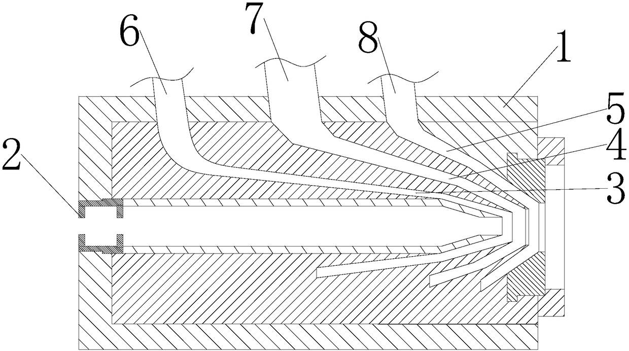
[0041] The invention provides a self-limiting temperature heating cable combined co-extrusion device, such as figure 1As shown, it includes a machine headstock 1, which is provided with a core base 2, a core set and a mold cover, the core set is installed on the core base 2, and the core set It includes a first mold core, a second mold core and a third mold core arranged coaxially, a first runner 3 is formed between the first mold core and the second mold core, and the second mold core and the A second runner 4 is formed between the third mold cores, and a third runner 5 is formed between the third mold core and the headstock 1 . A threading pipe is arranged inside the first mold core for passing through the two metal inner cores of the temperature-limiting heating cable. The diameter of the end of the first core is smaller than the diameter of the end of the second core, and the diameter of the end of the second core is smaller than the diameter of the end of the third core....

Embodiment 2

[0057] Different from Example 1, such as Figure 15 As shown, the contact part in this embodiment is set as a protrusion 5239, and the protrusion 5239 is provided on the end surface of the vibration core 5321 close to the electrical conversion assembly 52, and the shape of the protrusion 5239 is a triangle or a circle Arc shape, the protrusion 5239 in this embodiment is preferably set in an arc shape. When the contact end 546 is in contact with the vibration core 5321, the vibration core C53213 with a larger amplitude will push up the contact end 546, and when the amplitude of the adjacent vibration core D53214 increases, the contact end 546 will be The force of the vibrating core D53214, the side wall of the tooth groove 5463 on the contact end 546 is pressed upward by the vibration core D53214, so that the center of the tooth groove 5463 tends to be in line with the vibration The core D53214 is in contact with each other, thereby causing the contact end 546 to move laterall...

Embodiment 3

[0060] Since heating only through the hot water circulating in the heat pipe 9 has certain limitations, such as slow heating speed, in order to improve the heating efficiency, the difference between this embodiment and the first embodiment is that the temperature control device includes The heating ring arranged on the headstock 1, since there are three different wrapping materials circulating in the device, the temperature of each material entering the device is different, so the temperature is different at different positions of the device In the present invention, the heating ring is composed of a plurality of detachable heating plates to form a circular ring, and is covered on the headstock 1, and a control power supply and a temperature sensing probe are independently arranged on the heating plates, so The temperature sensing probe is used to detect the temperature at the position corresponding to the heating sheet, and the temperature sensing probe is connected to the con...


PUM


Abstract

The invention discloses a self-regulation heating belt combined coextrusion device. The device comprises a machine head base, a mold core base and a mold core set; and the mold core set is mounted onthe mold core base. The device is characterized in that the mold core set comprises a first mold core, a second mold core and a third mold core coaxially arranged; a first runner is formed between thefirst mold core and the second mold core; a second runner is formed between the second mold core and the third mold core; and a third runner is formed between the third mold core and the machine headbase. The self-regulation heating belt combined coextrusion device further comprises a temperature control device; the temperature control device comprises a temperature detecting device and a controller; the temperature detecting device is in communication connection with the controller; and an energy collecting device is arranged on the temperature detecting device. The device saves the energy,and can realize self energy supply of the temperature detecting device.

Description

technical field [0001] The invention relates to the technical field of production equipment, in particular to a combined co-extrusion device for a self-limiting temperature heating cable. Background technique [0002] With the continuous progress of society and the continuous improvement of automation, the application of heat tracing technology is becoming more and more extensive. The self-limiting temperature electric heating cable with the characteristics of positive temperature coefficient of resistance (ie PTC) has developed with its unique self-limiting temperature characteristics. Into the most versatile heating cable. At present, the self-limiting temperature heating cable is usually manufactured by a three-layer co-extrusion device, and the two conductive core structures are coated layer by layer, so that the PTC polymer material for heating is distributed between the two conductive cores, and the outer coating covered with a polymer insulating layer. [0003] In t...

Claims


Application Information

Patent Timeline
Patent Type & Authority Applications(China)
IPC IPC(8): B29C47/26B29C47/08B29C47/92H01B13/14
CPCH01B13/141H01B13/143
Inventor 计成志
Owner ANHUI HUANRUI ELECTROTHERMAL EQUIP
Why Eureka
Try Eureka