
A special switching device for realizing multi-channel signal output in icp constant current source circuit

A multi-channel signal and switching device technology, applied in the direction of electrical digital data processing, instruments, etc., can solve the problem of low utilization rate of sensor signals

Active Publication Date: 2021-05-28
CHINA SHIP DEV & DESIGN CENT
View PDF6 Cites 0 Cited by
  • Summary
  • Abstract
  • Description
  • Claims
  • Application Information

AI Technical Summary

Problems solved by technology

[0003] The technical problem to be solved by the present invention is to provide a special switching device for realizing multi-channel signal output in the ICP constant current source circuit, aiming at the relatively low utilization rate of the existing sensor signal. The signal is converted into a multi-channel voltage signal output without affecting the original circuit signal. When the output circuit has a short circuit, ICP power supply and other abnormal conditions, the original circuit will not be affected, so as to realize the needs of different data acquisition and analysis systems for the acquisition and analysis of the same ICP sensor signal. At the same time meet certain accuracy and system security requirements

Method used


Image

  • A special switching device for realizing multi-channel signal output in icp constant current source circuit
  • A special switching device for realizing multi-channel signal output in icp constant current source circuit
  • A special switching device for realizing multi-channel signal output in icp constant current source circuit

Examples


Embodiment Construction

[0024] The present invention will be further described in detail below in conjunction with the accompanying drawings and embodiments.

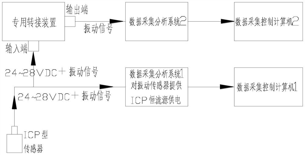
[0025] Refer to attached figure 1 As shown, the present invention is a special switching device for realizing multi-channel signal output in the ICP constant current source circuit, which is applied in the ICP constant current source circuit. The ICP constant current source circuit includes an ICP sensor (or IEPE sensor), a first The data acquisition and analysis system, the special switching device realizes the conversion of the ICP sensor signal input into multiple signal outputs for other data acquisition and analysis systems (such as the second data acquisition and analysis system), and the ICP sensor is powered by the first data acquisition and analysis system. The second data acquisition and analysis system does not need to be powered by the ICP constant current source again.

[0026] The special switching device is mainly composed of a...


PUM


Abstract

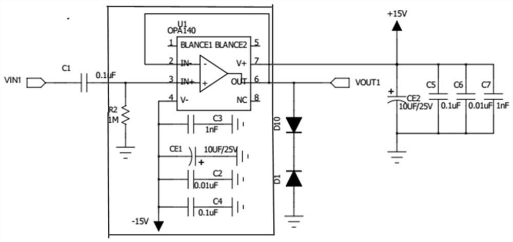
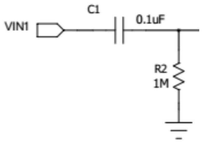
A special switching device for realizing multi-channel signal output in an ICP constant current source circuit, including a DC blocking circuit, an RC high-pass filter circuit, an emitter follower circuit and a reverse input protection circuit; the DC blocking circuit adopts a capacitor C1 connected in series to the input signal Between the interface and the output signal interface, it is used to filter out the DC voltage in the signal collected by the ICP sensor to obtain the sensor's alternating voltage signal; the RC high-pass filter circuit includes a resistor R2 and a capacitor C1, and the resistor R2 is connected in series with the ground before the signal output terminal Between the connection parts, it is used to prevent the voltage difference between the signal circuit and the ground. Capacitor C1 sets the filter frequency of the signal; the emitter follower circuit is used to enhance the signal current collected by the ICP sensor; the reverse input protection circuit is used for output protection against short circuits. The invention aims at converting one analog signal output by the ICP sensor into multiple voltage signal outputs without affecting the original circuit signal, and does not affect the original circuit when abnormal conditions such as short circuit and ICP power supply occur in the output circuit.

Description

technical field [0001] The invention relates to the field of ICP sensor signal transmission, in particular to a special switching device for realizing multi-channel signal output in an ICP constant current source circuit. Background technique [0002] With the widespread application of sensor technology, especially the widespread use of ICP or IEPE sensors, it has become the norm in the industry to use a large number of sensors and supporting data collection to monitor the operating status of mechanical equipment or systems. ICP or IEPE sensors require a data acquisition and analysis system for constant current power supply. Generally, a single signal corresponds to a separate data acquisition and analysis system, and the utilization rate of sensor signals is relatively low. Converting one ICP sensor signal into multiple voltage signal outputs for different data acquisition and analysis systems to achieve different analysis requirements is a technical problem that needs to b...

Claims


Application Information

Patent Timeline
Patent Type & Authority Patents(China)
IPC IPC(8): G06F13/40
CPCG06F13/4068
Inventor 潘亚军田波王冠沈渡张海江焦富清
Owner CHINA SHIP DEV & DESIGN CENT
Learn More