
Single-point control benefit evaluation method of road traffic signal

A single-point control and traffic signal technology, which is applied in the traffic control system of road vehicles, traffic control system, traffic signal control, etc., can solve problems such as the inability to establish a unified evaluation system, the lack of quantitative analysis methods, and uneven application levels

Inactive Publication Date: 2018-12-25
TRAFFIC MANAGEMENT RES INST OF THE MIN OF PUBLIC SECURITY
View PDF6 Cites 12 Cited by
  • Summary
  • Abstract
  • Description
  • Claims
  • Application Information

AI Technical Summary

Problems solved by technology

There are various types of signal control systems used in various places, and the control methods include timing, induction, self-adaptation, trunk line coordination, regional control, etc., and the application level is uneven. In order to control and manage traffic lights reasonably, it is necessary to apply traffic lights The effect and adaptability are evaluated and verified; due to the lack of a unified traffic signal control benefit evaluation specification in China, the current evaluation of the rationality of road intersection signal management is mainly to start with manual observation of the congestion situation of each road intersection, from each Judging the signal management of road intersections from the angles of vehicle queuing at each intersection and the number of vehicles passing through each green light, etc., but the methods used are all subjective judgment methods, lacking reasonable and general quantitative analysis methods. As for the inability to establish a unified evaluation system, unified and scientific control and management of traffic signals at intersections

Method used


Image

  • Single-point control benefit evaluation method of road traffic signal
  • Single-point control benefit evaluation method of road traffic signal
  • Single-point control benefit evaluation method of road traffic signal

Examples


Embodiment Construction

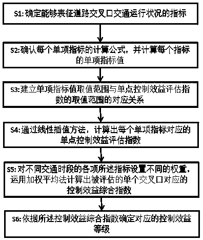
[0085] Such as figure 1 Shown, the technical scheme of the present invention is such, and it comprises following several steps.

[0086] S1: Through comprehensive analysis, relevant indicators that can characterize the road traffic operation status are determined. According to the principles of objectivity, practicability, and operability, the indicators that can characterize the management status of road intersections are determined.

[0087] S2: Confirm the calculation formula of the index and calculate the single index value of the index; the index used to characterize the road traffic operation status includes the queue length of key lanes, average driving delay, and green light utilization rate;

[0088] The key lane is the entrance lane that plays a decisive role in the traffic capacity of the entire intersection and the design of signal timing; the calculation method of the single index value of the key lane queuing length is the average of the vehicle queuing length on...


PUM


Abstract

The invention provides a single-point control benefit evaluation method of a road traffic signal. By the single-point control benefit evaluation method, quantized data can be provided, and the controlbenefit of a road intersection signal can be objectively evaluated. The signal-point control benefit evaluation method of the road traffic signal comprises the steps of S1, detecting an index which can represent a traffic running condition of a road intersection; S2, detecting a calculation formula of the index, and calculating a single index value of the index; S3, building a corresponding relation between a single index value range and a value range of a single-point control benefit evaluation index; S4, calculating a corresponding single-point control benefit evaluation index by a linear interpolation method; and S5, evaluating different emphasis points of traffic signal single-point control benefit with regard to different traffic time frames, and setting different weights for each index at different traffic time frames. On the basis of the sum of each single-point control benefit evaluation index and the corresponding weight, the control benefit integral index corresponding to asingle intersection is calculated by employing a weighted mean method.

Description

technical field [0001] The invention relates to the technical field of road intersection signal control effect evaluation, in particular to a road traffic signal single-point control benefit evaluation method. Background technique [0002] With the widespread application of intelligent transportation technology, traffic signal control technology has been developed on a large scale. According to statistics, by the end of 2016, there were 74,000 signal lights controlling intersections across the country, and the light control rate reached 43.1%. There are various types of signal control systems used in various places, and the control methods include timing, induction, self-adaptation, trunk line coordination, regional control, etc., and the application level is uneven. In order to control and manage traffic lights reasonably, it is necessary to apply traffic lights The effect and adaptability are evaluated and verified; due to the lack of a unified traffic signal control bene...

Claims


Application Information

Patent Timeline
Patent Type & Authority Applications(China)
IPC IPC(8): G08G1/01G08G1/07G06Q10/06
CPCG06Q10/0639G08G1/0125G08G1/07
Inventor 张雷元树爱兵马超锋王婷婷徐新东
Owner TRAFFIC MANAGEMENT RES INST OF THE MIN OF PUBLIC SECURITY
Learn More