A dryer for chemical fabric

A dryer and fabric technology, applied in dryers, drying, progressive dryers, etc., can solve the problems of high-temperature steam consumption, slow heating of the drying cylinder, and large steam consumption, so as to improve the utilization rate of heat energy. , The effect of small steam consumption and uniform surface temperature

Inactive Publication Date: 2018-12-28
湖州甬邦纺织品织造有限公司
View PDF0 Cites 3 Cited by
  • Summary
  • Abstract
  • Description
  • Claims
  • Application Information

AI Technical Summary

Problems solved by technology

[0002] At present, some chemical fiber fabric dryers that are common in the market usually dry the chemical fiber fabric through an oven, and multiple guide rollers and tension rollers are installed in the oven to increase the drying area of ​​the chemical fiber fabric in the oven, but This kind of equipment only discharges the water vapor in the oven through the inlet and outlet of the oven, especially the water vapor at the outlet of the oven will drip on the dried cloth again after being condensed by the air, seriously affecting the drying effect; Moreover, there is high heat energy in the water vapor in the oven, and the direct discharge of water vapor will lead to the problem of low heat energy utilization; at the same time, the drying cylinder of the existing equipment is directly fed with steam to raise the temperature, because the high-temperature steam is in the cylinder body. Liquefaction will occur when the inner wall of the cylinder is in contact, so that condensed water will be deposited at the bottom of the cylinder, and the temperature at the bottom of the cylinder is lower than that of other parts of the cylinder, resulting in uneven heating temperature on the surface of the drying cylinder; The inner cavity of the similar dryer is relatively large, and it needs to consume a large amount of steam to fill the dryer at one time. The steam needs to heat the gas inside the dryer first, and the inner wall of the dryer can be heated evenly. The temperature rise of the dryer is slower and the high temperature High steam consumption
Therefore, the existing chemical fiber cloth dryer has the problems of poor drying effect, low heat energy utilization rate, uneven heating temperature on the surface of the drying cylinder, slow temperature rise of the drying cylinder and large steam consumption.

Method used


Image

  • A dryer for chemical fabric
  • A dryer for chemical fabric
  • A dryer for chemical fabric

Examples


Embodiment Construction

[0018] The present invention will be further described below in conjunction with the accompanying drawings and embodiments, but not as a basis for limiting the present invention.

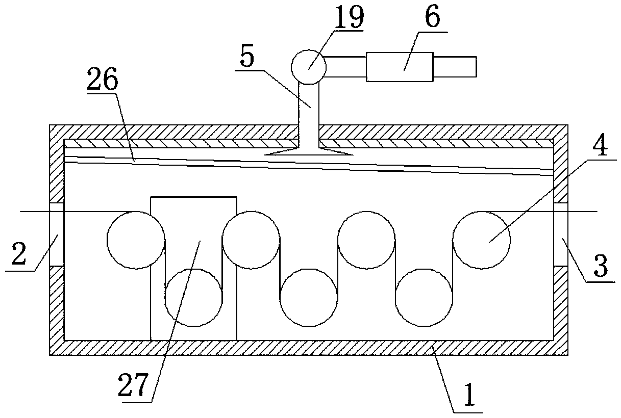
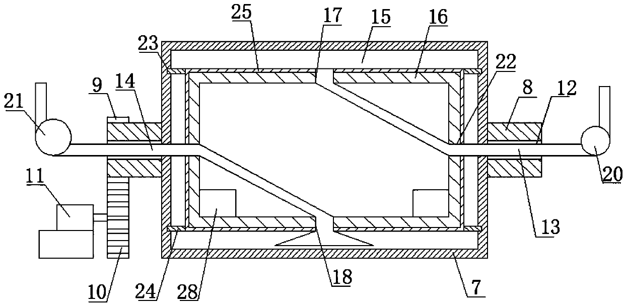
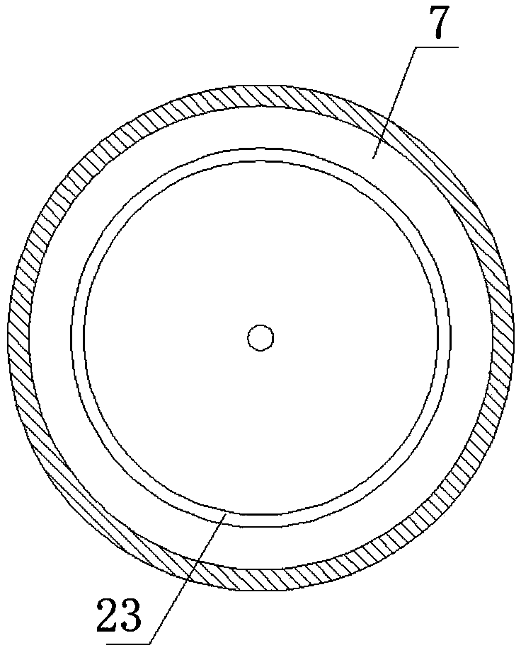
[0019] Example. A kind of chemical fiber cloth dryer, constituted as Figures 1 to 4 As shown, including an oven 1, the two ends of the oven 1 are respectively provided with a feed port 2 and a discharge port 3; the oven 1 is provided with upper and lower rows of drying cylinders 4, and the drying cylinders 4 in the upper row of drying cylinders 4 and the lower row of drying cylinders The drying cylinders 4 in the drying cylinders 4 are mutually staggered; the top of the oven 1 is connected with an exhaust pipe 5, and the exhaust pipe 5 is connected with a heat exchanger 6; Both sides are fixedly connected with a rotating shaft 8; the outside of the rotating shaft 8 on one side of the cylinder body 7 is fixedly connected with a ring gear 9, and a gear 10 is arranged below the ring gear 9; a driving...


PUM


Abstract

The invention discloses a chemical fabric dryer, which comprises an oven provided with two top and bottom drying cylinders which are interlaced with each other; an exhaust pipe is connected to the topof the oven and a heat exchanger is connected to it. The drying cylinder comprises a cylinder body fixedly connected with rotating shafts on both sides. A through hole is arranged in a middle portionof the rotating shaft on both sides of the cylinder body, wherein one of the through holes is provided with a steam pipe, and the other through hole is provided with an outlet pipe. A cavity with a hollow inner cylinder is in the cylinder body. The two sides of the inner cylinder are rotationally connected with the two sides of the cylinder body; the top of it is provided with an air inlet fixedly connected to the steam pipe; the bottom is provided with a outfall fixedly connected with the outlet pipe. The invention not only can improve the drying effect but has the advantages of high utilization of heat energy, uniform surface temperature and faster heating of the drying cylinder and less steam consumption as well.

Description

technical field [0001] The invention relates to a chemical fiber cloth drying equipment, in particular to a chemical fiber cloth drying machine. Background technique [0002] At present, some chemical fiber fabric dryers that are common in the market usually dry the chemical fiber fabric through an oven, and multiple guide rollers and tension rollers are installed in the oven to increase the drying area of ​​the chemical fiber fabric in the oven, but This kind of equipment only discharges the water vapor in the oven through the inlet and outlet of the oven, especially the water vapor at the outlet of the oven will drip on the dried cloth again after being condensed by the air, seriously affecting the drying effect; Moreover, there is high heat energy in the water vapor in the oven, and the direct discharge of water vapor will lead to the problem of low heat energy utilization; at the same time, the drying cylinder of the existing equipment is directly fed with steam to raise...

Claims


Application Information

Patent Timeline
Patent Type & Authority Applications(China)
IPC IPC(8): F26B13/14F26B23/10F26B25/00
CPCF26B13/145F26B23/10F26B25/00
Inventor 方仲华
Owner 湖州甬邦纺织品织造有限公司
Why Eureka
Try Eureka