
A fuel tank for rapid cook-off of wind-resistant ammunition

A fuel tank and fast technology, applied in the direction of ammunition, ammunition test, attack equipment, etc., can solve the problems of heavy oil pool, difficult to operate, easy to escape from the oil pool, and large depth of the oil pool, so as to save fuel for testing and test. Convenience, fuel consumption reduction effect

Active Publication Date: 2020-05-29
XIAN MODERN CHEM RES INST
View PDF8 Cites 0 Cited by
  • Summary
  • Abstract
  • Description
  • Claims
  • Application Information

AI Technical Summary

Problems solved by technology

[0006] In order to realize the purpose of the present invention, the concept of the present invention: in order to overcome the influence of the natural wind in the environment on the flame temperature stability, a flat-bottomed cubic uncovered square groove is made of a thin steel plate as an oil pool, and the depth of the groove is suitable for placing in the oil pool After the liquid fuel is ignited, the flame burns in the space in the oil pool and forms a stable 800°C fire field, but the oxygen required for fuel combustion and the high flame, which is easy to escape out of the oil pool and is affected by the ambient wind, must be solved. The depth of the pool is relatively large, causing problems such as the oil pool is too heavy and difficult to operate

Method used


Image

  • A fuel tank for rapid cook-off of wind-resistant ammunition
  • A fuel tank for rapid cook-off of wind-resistant ammunition
  • A fuel tank for rapid cook-off of wind-resistant ammunition

Examples


Embodiment 1

[0028] The present invention refers to figure 2 , image 3 , Figure 4 , Figure 5 , Figure 6 , Figure 7 implement.

[0029] 1.1 Manufacture of the present invention

[0030] The component materials used in the present invention are made of 45# steel or Q235 steel when not specified, and the surface is treated with anticorrosion.

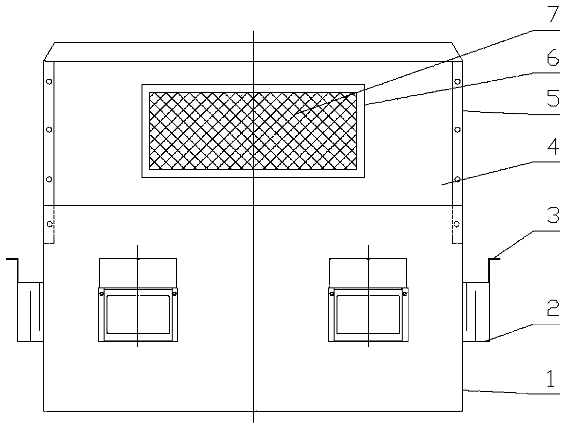
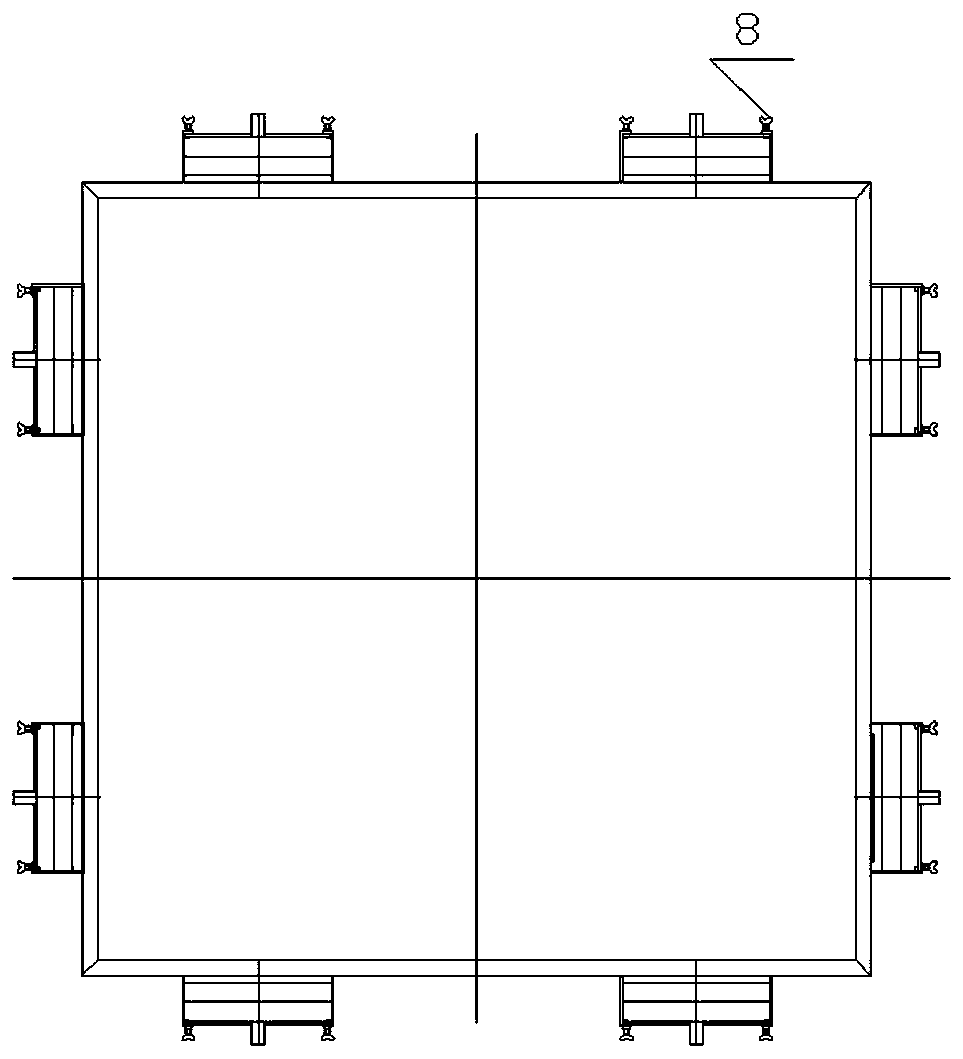
[0031]The oil pool 1 of the present invention is a flat-bottomed square groove without a top cover made by a 1mm-5mm thick steel plate, and two rectangular holes with a width of 50mm-170mm and a length of 70mm-180mm are respectively opened on the four walls. The liquid level of the liquid fuel is determined, the center line of the long side of the rectangular hole coincides with the length trisector of the tank wall, and at least one via hole with a diameter of 4mm-10mm is opened at each of the four corners near the upper edge of the notch;

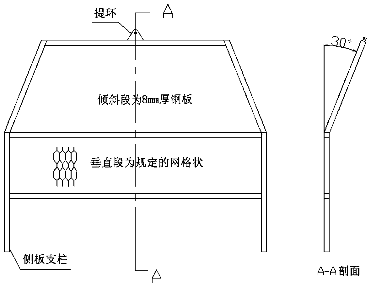
[0032] The air duct 2 of the present invention is a cubic box made of 1mm-5mm thick steel plates w...

Embodiment 2

[0044] The present invention refers to the attached image 3 , Figure 4 , Figure 5 , Figure 6 , Figure 7 , Figure 8 implement.

[0045] 2.1 Manufacture of the present invention

[0046] The manufacturing method of the present invention is basically the same as that of Embodiment 1, the difference is that the windshields 4 are connected by a connecting piece 5, and the windshields 4 and the oil pool 1 are connected by a connecting block 51:

[0047] The oil pool 1 of the present invention is basically the same as that of Embodiment 1, except that no via holes with a diameter of 4mm-10mm are opened near the upper edge of the notch at the four corners, and each side wall of the oil pool 1 is respectively opened near the upper edge. Two via holes with a diameter of 4mm-10mm, the position of the hole is consistent with the center position of the two rectangular holes on each side wall;

[0048] Air channel 2 of the present invention is identical with embodiment 1;

[0...

Embodiment 3

[0060] The present invention refers to the attached image 3 , Figure 4 , Figure 5 , Figure 6 , Figure 7 , Figure 9 implement.

[0061] 3.1 Manufacture of the present invention

[0062] The manufacturing method of the present invention is basically the same as that of Embodiment 1, except that the air duct 2 is composed of a net plate 61 and a bead 71:

[0063] Oil pool 1 of the present invention is identical with embodiment 1;

[0064] The stencil 61 of the present invention is a sieve plate made of 1mm-2mm steel wire, the mesh is diamond-shaped, and the diameter of the inscribed circle is 2mm-10mm. The stencil is made 10mm larger than the rectangular holes on the side wall of the oil pool 1. -20mm rectangle;

[0065] Layering bar 71 of the present invention is that 2mm-5mm thick steel plate is made the steel bar of wide 8mm-15mm;

[0066] 3.2 Assembly of the present invention

[0067] The assembly of the present invention is basically the same as that of Embod...


PUM

PropertyMeasurementUnit
Diameteraaaaaaaaaa
Heightaaaaaaaaaa
Hem widthaaaaaaaaaa

Abstract

The invention discloses a wind-resistant-type fuel tank for rapid cook-off of ammunition. The wind-resistant-type fuel tank comprises an oil pool, wind adjusting devices, wind baffles and connecting pieces and is characterized in that the two wind adjusting devices are arranged outside each of the four side walls of the oil pool, the wind baffles are arranged on the oil pool, and the lower edge ofeach wind baffle is in butted connection with the upper edge of the corresponding side wall of the oil pool; a right angle constituted by each right angle of the oil pool and the two corresponding wind baffles in a connected mode is internally (externally) provided with the corresponding connecting piece; rectangular holes are formed in the centers of one or more of the four wind baffles, net plates are arranged on the outer sides of the holes, and flat iron is arranged outside each net plate. The wind-resistant-type fuel tank for rapid cook-off of the ammunition is mainly used for solving the problems that due to the significant influence of environment strong wind on flames, an ammunition cook-off test cannot be conducted, the test cost is high, and fuel consumption is high, the fuel tank suitable for the strong wind condition, small in weight, low in cost and low in fuel consumption amount can be obtained, and the wind-resistant-type fuel tank is mainly used for explosive and ammunition rapid cook-off tests.

Description

technical field [0001] The invention relates to a fuel tank for rapid cook-off of wind-resistant ammunition, which belongs to the technical field of risk assessment of insensitive ammunition. Background technique [0002] With the development of ammunition technology in our country, the insensitivity of ammunition has been paid attention to. The fast cook-off performance parameter of ammunition is one of the main parameters to characterize the insensitivity of ammunition. The fast cook-off method of ammunition is a test method to obtain the performance parameters of fast cook-off of ammunition. This method requires the test sample to evaluate the response state in an environment with an average flame temperature greater than 800°C. It is quite difficult to achieve the above-mentioned flame environment. In China, wood is generally piled up and then ignited to obtain the temperature field, but this is not reliable, because the flame temperature is not uniform, and it is diffi...

Claims


Application Information

Patent Timeline
IPC IPC(8): F42B35/00
CPCF42B35/00
Inventor 王晓峰南海段伯祯郭昕夏青孙培培席鹏高立龙
Owner XIAN MODERN CHEM RES INST
Features
  • Generate Ideas
  • Intellectual Property
  • Life Sciences
  • Materials
  • Tech Scout
  • Unparalleled Data Quality
  • Higher Quality Content
  • 60% Fewer Hallucinations
Learn More