Gain dynamic control method, device and system of Raman fiber amplifier

A Raman optical fiber and dynamic control technology, which is applied to lasers, transmission systems, laser components, etc., can solve problems such as changes in optical power of optical fiber lines, achieve short completion times, and maintain gain stability

Active Publication Date: 2018-12-28
GUANGXUN SCI & TECH WUHAN
View PDF12 Cites 6 Cited by
  • Summary
  • Abstract
  • Description
  • Claims
  • Application Information

AI Technical Summary

Problems solved by technology

[0005] The technical problem to be solved by the present invention is that in the prior art, the increase and decrease of the optical channel on the line often occurs, which will cause frequent and drastic changes in the total optical power on the optical fiber line

Method used


Image

  • Gain dynamic control method, device and system of Raman fiber amplifier
  • Gain dynamic control method, device and system of Raman fiber amplifier
  • Gain dynamic control method, device and system of Raman fiber amplifier

Examples


Embodiment 1

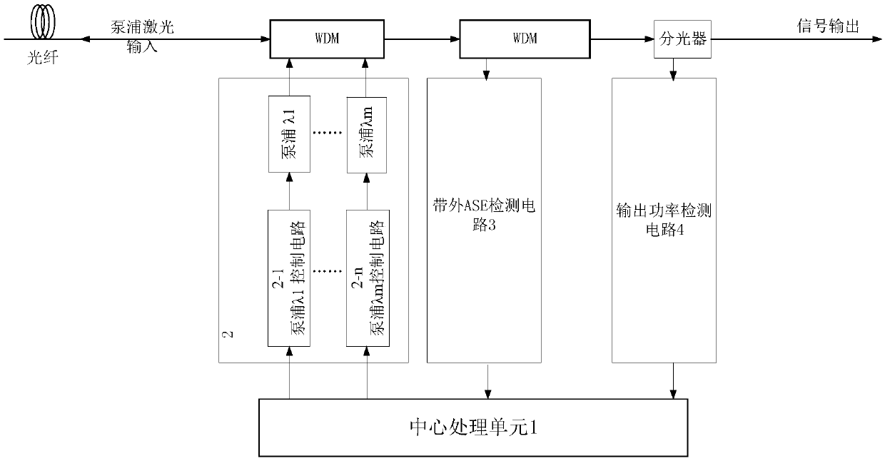
[0062] Embodiment 1 of the present invention provides a gain dynamic control system of a Raman fiber amplifier, such as figure 1 As shown, it includes a Raman fiber amplifier 2 composed of one or more pump lasers (λ1,...,λn), and a control circuit (2-1,... , 2-n), corresponding to the Raman fiber amplifier 2 is also provided with an out-of-band ASE detection circuit 3 and an output power detection circuit 4, wherein the control circuit (2-1, ..., 2-n) of the pump laser, The out-of-band ASE detection circuit 3 and the output power detection circuit 4 are respectively connected to the central processing unit 1, and the system specifically includes:

[0063] Configure the system so that the Raman amplified input signal optical power is at the maximum input power when the pump is turned off, and the central processing unit 1 sets the output optical power of all pump lasers to the maximum output pump power to obtain the current Raman amplifier Gain G M and gain slope tilt M ;

...

Embodiment 2

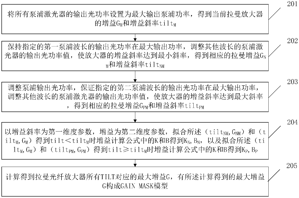
[0083] After the embodiment of the present invention provides a dynamic gain control system for a Raman fiber amplifier as described in Embodiment 1, the embodiment of the present invention also proposes a corresponding dynamic gain control method for a Raman fiber amplifier, specifically The solution can be implemented in the system in Embodiment 1, and can also be applied to other systems similar to the system architecture described in Embodiment 1, and there is no special limitation here. Such as figure 2 As shown, the methods include:

[0084] In step 201, the output optical power of all pump lasers is set to the maximum output pump power, and the gain G of the current Raman amplifier is obtained M and gain slope tilt M .

[0085] Wherein, the step 201 is usually implemented under the following constraints: the system is configured so that the optical power of the Raman-amplified input signal is at the maximum input power when the pump is turned off.

[0086] In step ...

Embodiment 3

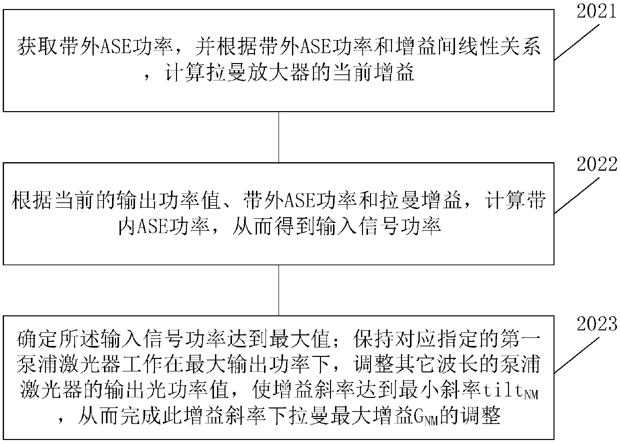
[0106] The embodiment of the present invention also provides an implementation solution for the GAINMASK proposed in Embodiment 2 of the present invention in a specific application scenario. Wherein, the specific application scenario refers to the function that the GAIN MASK is set as an optional configuration, then the method needs to judge whether the GAIN MASK is capable or not during the specific implementation process, so as to complete the entire solution process. Specifically, it will be described in conjunction with the system shown in Embodiment 1, as Figure 5 shown, including:

[0107] In step 401, the central processing unit 1 judges the GAIN MASK enabling state of the Raman amplifier, and judges whether the target gain is limited within the gain range of the GAIN MASK according to the state of the GAIN MASK.

[0108] When the GAIN MASK enabling state is enabled; if the target gain is not greater than the GAIN MASK, step 403 is executed, and the central processing...


PUM


Abstract

The invention relates to the technical field of Raman fiber amplifiers, and provides a gain dynamic control method, device and system of a Raman fiber amplifier. The method includes: determining whether the target gain is within the range of GAIN MASK; if the target gain is within the GAIN MASK range, directing locking the same to the target gain; if the target gain is within or outside the GAIN MASK range, locking the gain to the maximum value of the corresponding GAIN MASK gain, and then increasing the locked gain progressively according to a preset first step length until the target gain isreached or at least one pumped laser is present to reach the maximum output power. The invention achieves the effect that the amplifier in the optical fiber line can quickly respond to the change ofthe input optical signal, maintains the gain stability, prevents the optical channel without switching in the line from generating excessive power overshoot or undershoot, and on the other hand, whenthe gain switching occurs, the completion time of the switching is as short as possible.

Description

【Technical field】 [0001] The invention relates to the technical field of Raman fiber amplifiers, in particular to a method, device and system for dynamic gain control of Raman fiber amplifiers. 【Background technique】 [0002] With the rapid development of video services, big data, 5G and the Internet of Things, the system has more and more urgent demands on the network capacity of the backbone network. The 100Gbit / s system can no longer fully meet the bandwidth requirements. Systems exceeding 100Gbit / s, such as 400Gbit The / s system is being trialed on a small scale, and the super 100Gbit / s system has higher and higher requirements for OSNR (Optical Signal Noise Ratio, abbreviated as: OSNR). Distributed Raman Amplifier (DRA for short) is being more and more widely used in ultra-high-speed, ultra-large-capacity, and ultra-long-distance optical fiber communication systems due to its extremely low equivalent noise index advantages middle. At the same time, in order to support...

Claims


Application Information

Patent Timeline
Patent Type & Authority Applications(China)
IPC IPC(8): H01S3/13
CPCH01S3/1301H04B10/2916H01S2301/02H01S3/10069H01S3/13013H01S3/0912H01S3/094096H01S3/06754H01S3/302H01S3/094003H01S2301/04
Inventor 张翠红付成鹏陶金涛张皓程丽晶
Owner GUANGXUN SCI & TECH WUHAN
Why Eureka
Try Eureka