Electric motor

A body and component technology, applied in the direction of electromechanical devices, electrical components, mechanical equipment, etc., can solve the problems of reducing the efficiency and performance of motors

Active Publication Date: 2018-12-28
DYSON TECH LTD
View PDF6 Cites 10 Cited by
  • Summary
  • Abstract
  • Description
  • Claims
  • Application Information

AI Technical Summary

Problems solved by technology

This can reduce the efficiency and performance of the motor

Method used


Image

  • Electric motor
  • Electric motor
  • Electric motor

Examples


Embodiment Construction

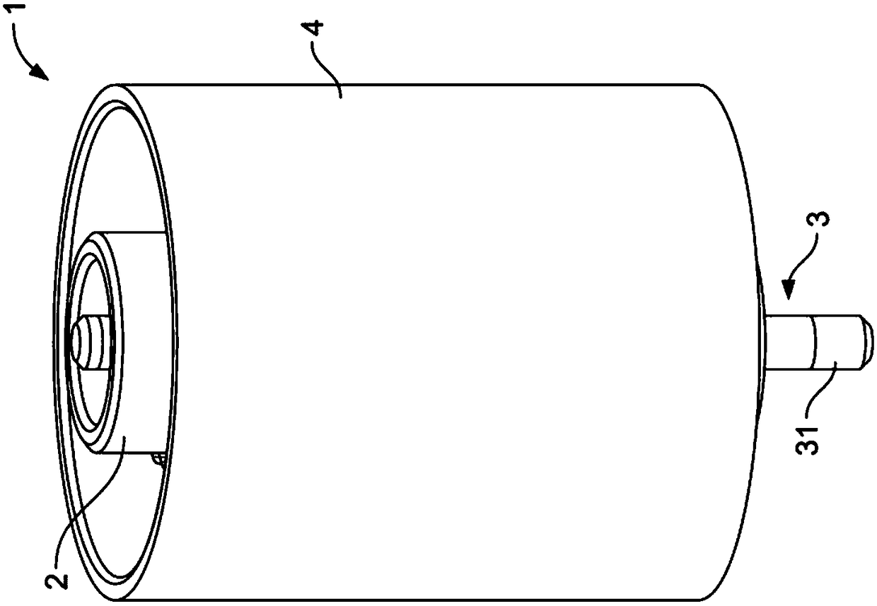
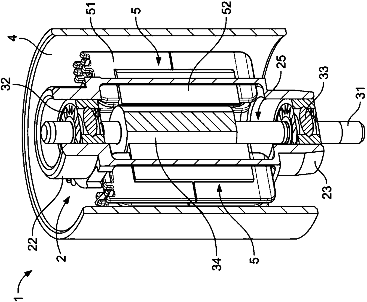
[0026] figure 1 with 2 The motor 1 includes a stator assembly, a rotor assembly 3 and a support body 2. The outer casing 4 surrounds the stator assembly, the rotor assembly 3 and the support body 2.

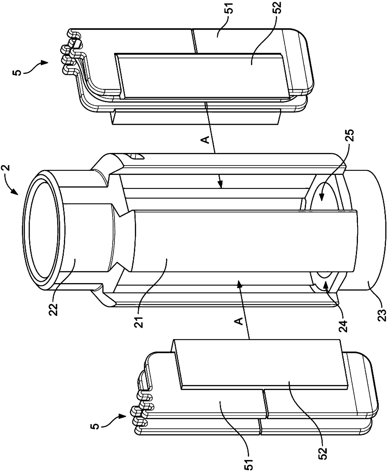
[0027] The stator assembly includes four stator elements 5, and each stator element 5 includes a c-shaped stator core 52 and a bobbin 51 fixed to the c-shaped stator core 52. Each stator element 5 is fixed to the support body 2, the details of which will be described in more detail below.

[0028] The rotor assembly 3 includes a shaft 31, bearings 33 and 33, and a magnet 34. Bearings 32, 33 are installed at both ends of the magnet 34. The magnet 34 is a permanent magnet of the type commonly used in brushless permanent magnet motors.

[0029] Support body 2 (which can be image 3 It can be seen more clearly in) is a cylindrical shape, and includes an elongated central portion 21, and first and second bearing seats 22, 23, which are axially positioned at each end of the elongated centr...


PUM


Abstract

An electric motor comprising a stator assembly; a rotor assembly; and a support body. The stator assembly comprises a plurality of stator elements having poles and coils, and the rotor assembly comprises a shaft to which is mounted at least a first and a second bearing mounted either side of a permanent magnet. The support body comprises an elongate central part, and first and second bearing seatspositioned axially at opposite ends of the elongated central part to each other, and the elongate central part defines a plurality of openings each configured to receive one of the plurality of stator elements secured by welding or adhesive. The body may have reinforcing ribs and one of the bearing supports may mount a fan shroud for a compressor application.

Description

Technical field [0001] The invention relates to a motor. Background technique [0002] The motor usually includes a rotor assembly, a stator assembly, and a frame that holds the components together. The stator assembly is usually mounted to the frame using a stator core. This allows the positioning of the stator core relative to other components of the motor (such as the rotor assembly) to be accurately controlled. However, using the stator core as a structural component to achieve precise positioning of the motor components requires that the stator core be manufactured to be strong and have very high tolerances. This can result in the stator core being bulky, heavy and expensive to manufacture. In addition, requiring such stator cores to include mounting structures, such as through holes and / or cut-outs, can lead to magnetic "pinch points" where high levels of magnetic saturation can occur during motor operation. This can reduce the efficiency and performance of the motor. ...

Claims


Application Information

Patent Timeline
Patent Type & Authority Applications(China)
IPC IPC(8): H02K1/18H02K1/28H02K5/16
CPCH02K1/185H02K1/28H02K5/161H02K5/1732H02K7/083H02K7/14H02K2213/03H02K1/141H02K5/128H02K5/20H02K1/17H02K1/20F04D25/082H02K5/04
Inventor A.C.克洛西尔G.F.金
Owner DYSON TECH LTD
Why Eureka
Try Eureka