A thin receiver
A receiver and thin technology, applied in the direction of sensors, sensor parts, frequency/direction characteristic devices, etc., can solve the problem of low frequency response of receiver sound, achieve the effect of improving frequency response and sound performance
- Summary
- Abstract
- Description
- Claims
- Application Information
AI Technical Summary
Problems solved by technology
Method used
Image
Examples
Embodiment 1
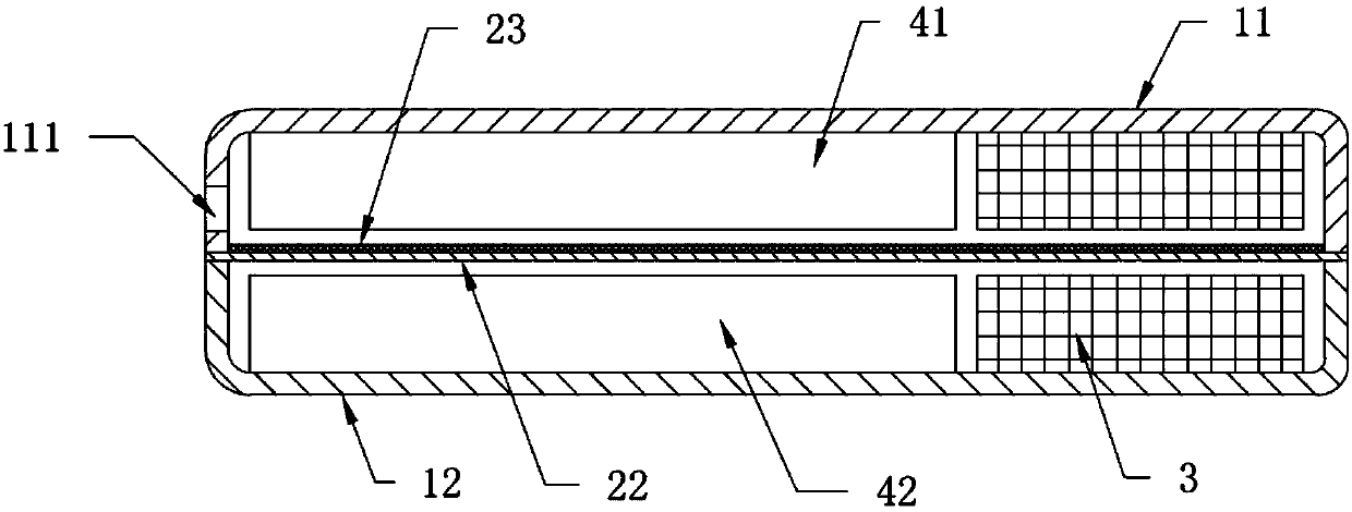
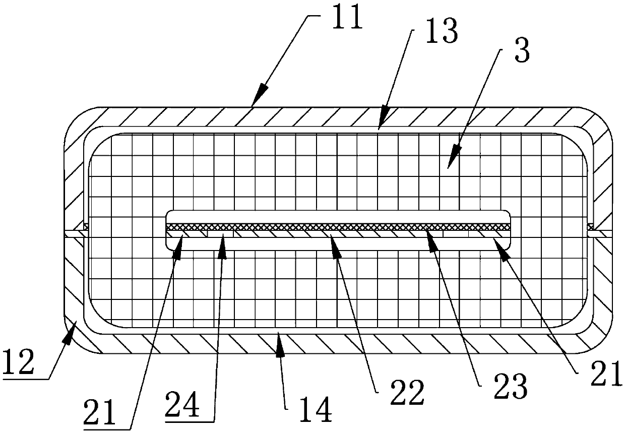
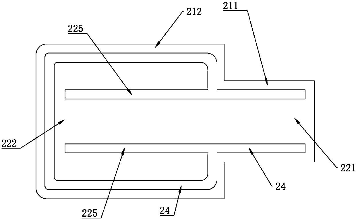
[0055] This embodiment provides a thin receiver, such as Figure 1 to Figure 4 As shown, it includes a casing 1, a diaphragm assembly, a coil 3 and two permanent magnets.
[0056] Wherein, the casing 1 includes a first housing 11 and a second housing 12 respectively having openings, the opening at the bottom of the first housing 11 is opposite to the opening at the top of the second housing 12 and is buckled and fixed to form a closed Install the cavity. Optionally, both the first casing 11 and the second casing 12 are made of high-permeability materials, such as high-permeability nickel alloy materials.
[0057] Such as figure 2 , image 3 and Figure 4 As shown, the diaphragm assembly includes a frame-shaped frame 21, a diaphragm 22 and a sealing film 23. The frame-shaped frame 21 is sandwiched between the openings of the first shell 11 and the second shell 12, for example, by laser welding The bottom opening of the first casing 11 , the frame frame 21 and the top open...
Embodiment 2
[0094] This embodiment provides a thin receiver, which differs from the receiver provided in Embodiment 1 in that:
[0095] Such as Image 6 with Figure 7 As shown, the diaphragm 22 includes a diaphragm body 223 and a reed 224. One end of the diaphragm body 223 is formed on the frame frame 21, and the other end is suspended in the inner cavity of the frame frame 21. The diaphragm body 223 and the frame frame A first gap 24 is formed between the frames 21, the diaphragm body 223 is made of a non-magnetic material, such as a highly elastic lightweight material, such as aluminum-magnesium alloy, aluminum alloy and other materials, and the reed 224 is made of a soft magnetic material; The sealing film 23 is fixed on the diaphragm body 223 and the frame 21 to cover all the first gaps 24 . Optionally, the diaphragm body 223 also includes a first part and a second part similar to the diaphragm in Embodiment 1. Or the sealing film is fixed on the frame frame, the reed and the diap...
Embodiment 3
[0100] This embodiment provides a thin receiver, which differs from the receiver in Embodiment 1 or Embodiment 2 in that:
[0101] On the basis of the technical scheme of embodiment 1 or on the basis of the technical scheme of embodiment 2, such as Figure 11 As shown, two first extensions 213 bent toward the second cavity are provided on the side wall where the frame 21 connects with the wall of the inner hole of the coil 3 . That is, the two ends of the first installation part 211 are respectively provided with a first extension part 213 bent toward the second cavity, the coil 3 is sleeved outside the two first extension parts 213, and the two side walls of the inner hole of the coil 3 They are respectively sealed and fixed with the outer wall surface of a first extension part 213 .
[0102] In this embodiment, by setting the first extension part 213 on the first mounting part of the frame frame 21, the firmness of the sealing connection between the wall surface of the inne...
PUM
 Abstract
Description
Claims
Application Information
 - R&D
- Intellectual Property
- Life Sciences
- Materials
- Tech Scout
- Unparalleled Data Quality
- Higher Quality Content
- 60% Fewer Hallucinations
Browse by: Latest US Patents, China's latest patents, Technical Efficacy Thesaurus, Application Domain, Technology Topic, Popular Technical Reports.
© 2025 PatSnap. All rights reserved.Legal|Privacy policy|Modern Slavery Act Transparency Statement|Sitemap|About US| Contact US: help@patsnap.com


