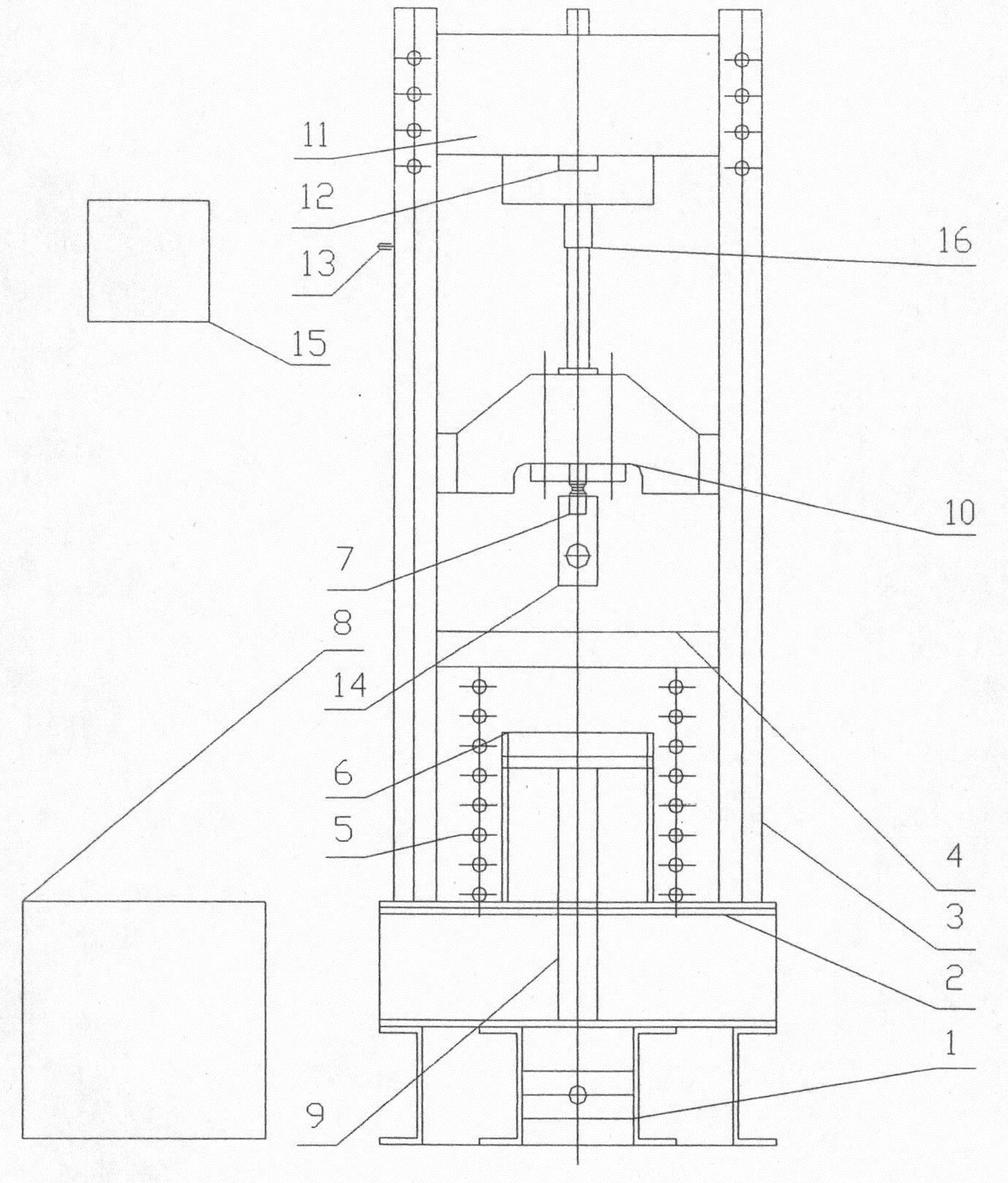
Test device for missile metal brake cone buffer
A technology of a test device and a brake cone, which is applied in the test of ammunition, the test of machine/structural components, and the measurement device, etc., can solve the problems of poor test repeatability, high potential safety hazards and low work efficiency, and shorten the development time. Time, high work efficiency, and the effect of ensuring product quality
Active Publication Date: 2012-07-18
SHANGHAI SPACE PRECISION MACHINERY RES INST
View PDF0 Cites 7 Cited by
- Summary
- Abstract
- Description
- Claims
- Application Information
AI Technical Summary
Problems solved by technology
In order to solve the deficiencies of the prior art, such as low work efficiency, large test safety hazards, high test cost, and poor test repetition consistency, the object of the invention is to provide a test device for a missile metal brake cone buffer, using Hooke's law and material The principle of mechanical shearing solves the above difficulties one by one, and provides a technical guarantee for the simulation test for the rapid design and finalization of the metal brake cone
Method used
View moreImage
Smart ImageViewing Examples
Examples
Embodiment Construction
Login to View More PUM
 Abstract
A test device for a missile metal brake cone buffer, comprising; a body including a base on which two pairs of four guide rails are installed; impact blocks are installed between the guide rails; the center of the base has a guide protective sleeve, and There is a hydraulically controlled actuator connected to the hydraulic loading system; the guide protective sleeve is covered with energy storage springs; the buffer beams and the brake cone installation bases are installed on the guide rails on both sides, and there are load cells inside; A speed sensor is installed; a high-strength steel block is installed at the bottom of the impact block, and a shear bolt is installed in the center of the steel block, and the shear bolt is installed between the impact block and the actuator. The invention solves problems such as the determination of the dynamic mechanical properties of the brake cone in the development process of the missile metal brake cone, achieves rapid verification of the mechanical properties of the metal brake cone, shortens the development cycle, reduces test risks, improves test safety and test accuracy, etc. Beneficial effect.
Description
technical field The invention relates to a test device for missile launching equipment, in particular to a test device for simulating and evaluating the dynamic mechanical characteristics of a missile metal braking cone buffer. Background technique In the missile launch test, the metal brake cone was used as a buffer to protect the internal launching mechanism of the missile from being damaged by the gas momentum or rushing out of the box after the missile was separated from the launch box. In order to ensure the reliable operation of the weapon system, the dynamic mechanical characteristics of the metal brake cone of the buffer mechanism need to be simulated and assessed. At present, the known simulation test devices for metal brake cones as buffers mainly use gas electric squibs or gas gunpowder to test the dynamic mechanical characteristics of brake cones. Although there is no problem with the authenticity of the simulation, there is a risk that the work site will be mor...
Claims
Login to View More Application Information
Patent Timeline
 Patent Type & Authority Patents(China)
IPC IPC(8): G01M7/08F42B35/00
Inventor 曹雪峰周改超
Owner SHANGHAI SPACE PRECISION MACHINERY RES INST
Features
- R&D
- Intellectual Property
- Life Sciences
- Materials
- Tech Scout
- Unparalleled Data Quality
- Higher Quality Content
- 60% Fewer Hallucinations
Learn More Browse by: Latest US Patents, China's latest patents, Technical Efficacy Thesaurus, Application Domain, Technology Topic, Popular Technical Reports.
© 2025 PatSnap. All rights reserved.Legal|Privacy policy|Modern Slavery Act Transparency Statement|Sitemap|About US| Contact US: help@patsnap.com

