Preparation apparatus of fiber reactive dye

A technology for reactive dyes and preparation devices, which is applied in transportation and packaging, mixers with rotating containers, dissolution, etc., can solve the problems of no protective dustproof device, uneven stirring, large power consumption, etc. High mobility, accelerated stirring effect, and low power consumption

Inactive Publication Date: 2019-01-01
陈旭东
View PDF0 Cites 0 Cited by
  • Summary
  • Abstract
  • Description
  • Claims
  • Application Information

AI Technical Summary

Problems solved by technology

[0002] In the current method of fabricating reactive dyestuffs, a simple rotating stirring device is usually used for stirring, which makes the stirring uneven, resulting in poor accuracy of dye production. Secondly, when the dye stirring device is not in use, there is no protective dustproof device. During the dye stirring process It has been affected, and it will also affect the dye manufacturing accuracy. In addition, the high-precision device has a complicated structure, consumes a lot of power, and is not easy to repair and clean. Therefore, there is an urgent need for a safe, efficient and automated fiber-reactive dye preparation device.

Method used


Image

  • Preparation apparatus of fiber reactive dye
  • Preparation apparatus of fiber reactive dye
  • Preparation apparatus of fiber reactive dye

Examples


Embodiment Construction

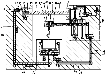
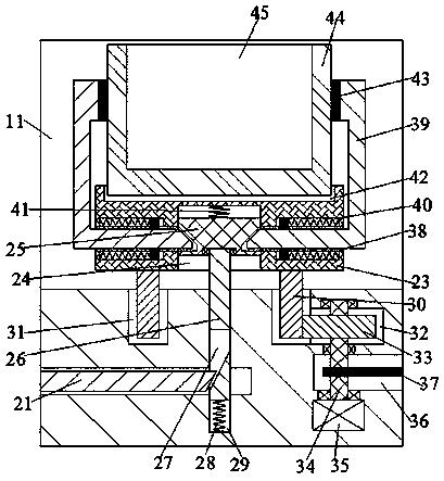
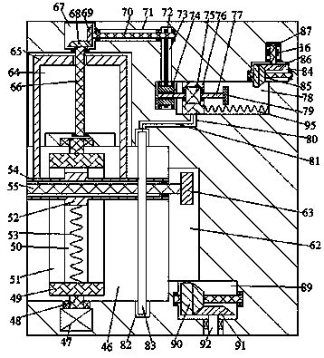
[0011] Combine below Figure 1-3 The present invention will be described in detail.

[0012] refer to Figure 1-3 , according to an embodiment of the present invention, a preparation device for a fiber-reactive dye includes a body 10, a cavity 11 with an opening facing upward is provided in the body 10, and the cavity 11 is symmetrically connected with an opening facing inward And the annular groove 12 that the rear side communicates with the outside world is provided with a closed cover 61 in the annular groove 12, and the left side of the annular groove 12 on the left side communicates with a lifting and rotating cavity 13 with an opening facing the right, and the closed cover 61 The left end extends into the lifting rotary cavity 13 and is fixedly provided with a lifting rotary block 14, and the upper end of the lifting rotary block 14 is fixedly provided with a first rotating shaft 15 that is rotatably connected to the upper end wall of the lifting rotary cavity 13. The ...


PUM


Abstract

The invention discloses a preparation apparatus of fiber reactive dye. The preparation apparatus comprises a machine body, wherein a cavity with an opening facing upwards is formed in the machine body, the cavity is laterally symmetrically provided with an annular groove with an opening facing inwards and with the rear side communicated with exterior, a sealing cover is arranged in the annular groove, the left side of the annular groove on the left side is provided with a lifting rotating cavity with an opening facing rightwards in a communication manner, the left end of the sealing cover stretches into the lifting rotating cavity and is fixedly provided with a lifting rotating block, and a first rotating shaft with the upper end being rotatably connected with the upper end wall of the lifting rotating cavity is fixedly arranged on the axis of the lifting rotating block. The preparation apparatus of the fiber reactive dye is simple in structure and convenient in operation; the dye canbe prevented from splashing outwards by virtue of the sealing cover, and the cleanliness in the cavity can be protected; and a storage box is stably locked onto the rotating block by virtue of a sliding rod apparatus, and then the storage box is driven by a rotating apparatus to rotate in a direction opposite to a crankshaft, so that the stirring effect of the dye can be improved, and the preparation apparatus is high in structure motility, small in electric energy consumption, environmentally friendly and high in efficiency.

Description

technical field [0001] The invention relates to the technical field of stirring, in particular to a preparation device for fiber reactive dyes. Background technique [0002] In the current method of fabricating reactive dyestuffs, a simple rotating stirring device is usually used for stirring, which makes the stirring uneven, resulting in poor accuracy of dye production. Secondly, when the dye stirring device is not in use, there is no protective dustproof device. During the dye stirring process It has been affected, and it will also affect the dye manufacturing accuracy. In addition, the high-precision device has a complicated structure, consumes a lot of power, and is not easy to repair and clean. Therefore, a safe, efficient and automated fiber reactive dye preparation device is urgently needed. Contents of the invention [0003] The object of the present invention is to provide a preparation device for fiber reactive dyes, which is used to overcome the above-mentioned ...

Claims


Application Information

Patent Timeline
Patent Type & Authority Applications(China)
IPC IPC(8): B01F9/12B01F15/00B01F29/83
CPCB01F29/40B01F29/83B01F35/324B01F35/325B01F35/3215B01F35/40B01F35/453B01F35/3204B01F2101/30
Inventor 陈旭东
Owner 陈旭东
Why Eureka
Try Eureka