Laminaria japonica cutting equipment

A cutting equipment and kelp technology, which is applied in metal processing and other directions, can solve the problems of kelp curling and cutting knives easily scratching the conveyor belt, and achieve the effects of reducing damage, improving cutting quality, and ensuring cutting quality

Pending Publication Date: 2019-01-01
福建省天源水产集团有限公司
View PDF1 Cites 8 Cited by
  • Summary
  • Abstract
  • Description
  • Claims
  • Application Information

AI Technical Summary

Problems solved by technology

Existing kelp cutting equipment, such as the Chinese utility model patent application number 201721564933.9 discloses a kelp cutting equipment, including a cutting box, a conveyor belt, a dust extraction hood, and a cutting knife, and one side of the inside of the cutting box is installed There is a stepper motor, a frame body is installed at the middle position below the inside of the cutting box, and rollers are evenly installed inside the frame body, the output end of the stepper motor is connected with the roller through a pulley structure, and the roller A conveyor belt is installed on the outside of the cylinder, and through holes are evenly arranged on the conveyor belt, and a finished product warehouse is installed on the side far away from the stepping motor at the bottom of the cutting box, and the kelp is moved and cut through the fixed pressure roller. Fix it to prevent the kelp from shifting, but the conveyor belt and kelp are always moving when cutting, and the cutting knife is easy to scratch the conveyor belt, which makes the rear kelp move hindered and curl

Method used


Image

  • Laminaria japonica cutting equipment
  • Laminaria japonica cutting equipment
  • Laminaria japonica cutting equipment

Examples


Embodiment

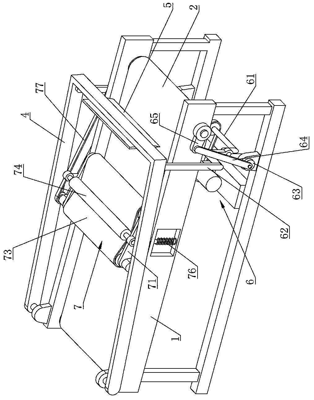
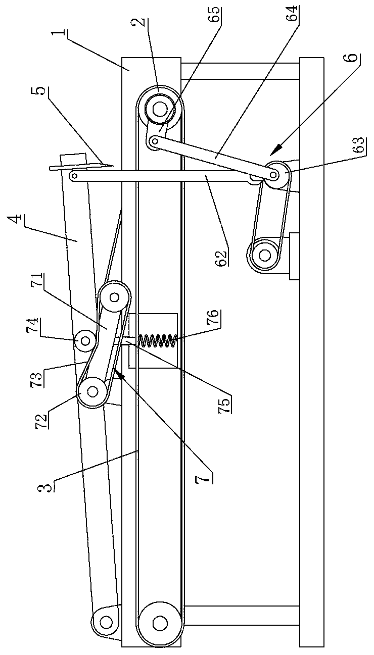
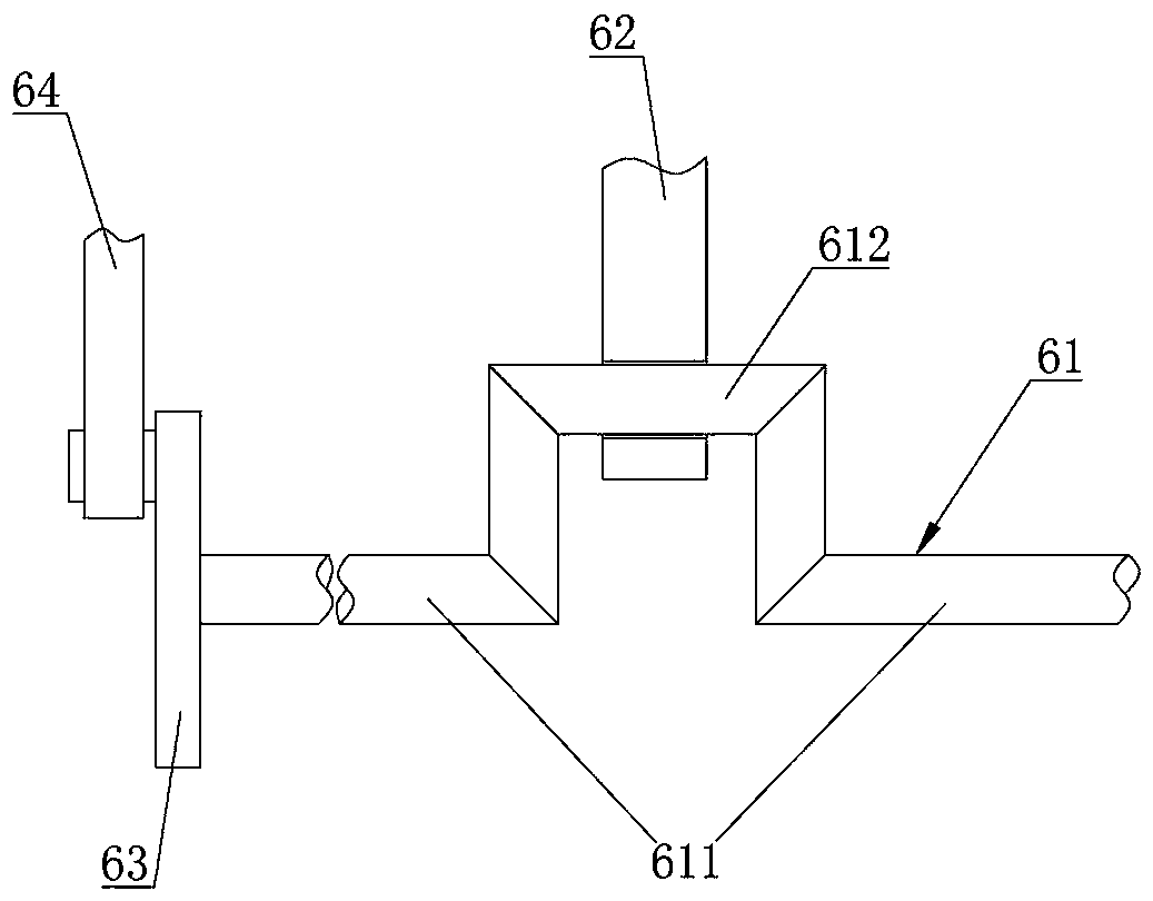
[0025] Example: such as Figure 1 to Figure 4 Shown, a kind of kelp cutting equipment comprises frame 1, the conveying roller 2 that is arranged on frame 1 front and rear ends, the conveyer belt 3 that is wound between the two conveying rollers 2 before and after, is arranged on the cutting machine above conveyer belt 3 Knife 5 and driving mechanism 6 that drives cutting knife 5 to move up and down and conveying roller 2 to rotate. The driving device at least includes a main shaft 61, the main shaft 61 rotates below the installation frame 1, a support frame 62 that drives the cutting knife 5 to move up and down is connected between the main shaft 61 and the cutter 5, and the upper end of the support frame 62 is fixedly connected with a cutting tool. The knife 5 is hinged at the eccentric position of the main shaft 61 at its lower end. The frame 1 is provided with a knife rest 4 , the front end of the knife rest 4 is hinged on the support frame 62 , and its rear end is hinged ...


PUM


Abstract

The invention relates to laminaria japonica cutting equipment. The equipment comprises a rack, conveying rollers, a conveying belt, a cutting tool and a driving mechanism. The driving mechanism at least comprises a main shaft. A supporting frame driving the cutting tool to move up and down is connected between the main shaft and the cutting tool. The lower end of the supporting frame is hinged tothe eccentric position of the main shaft. The conveying rollers rotate in an intermittent mode and drive the conveying belt to move forwards in an intermittent mode. An intermittent transmission mechanism used for controlling the conveying belt to stop or move when the cutting tool is located in a cutting position or a non-cutting position is connected between the main shaft and the conveying rollers. According to the laminaria japonica cutting equipment provided by the invention, the conveying belt moves in the intermittent mode, both laminaria japonica and the conveying belt are kept in a stationary state when the cutting tool cuts downwards, damage of the cutting tool to the conveying belt is reduced, and the laminaria japonica cutting quality is guaranteed; the cutting tool and the conveying rollers are driven by the same driving mechanism and are high in moving synchronism, and the equipment operating stability is high; and a pressing device can be used for stretching the laminaria japonica to be flat, it is guaranteed that the cutting width of the laminaria japonica each time is the same, and the cutting quality is improved.

Description

technical field [0001] The invention relates to the technical field of kelp processing equipment, in particular to a kelp cutting equipment. Background technique [0002] After the kelp is picked from the sea, it needs to go through a series of processing, one of which is to cut the kelp into kelp segments of the same size for easy packaging. Existing kelp cutting equipment, such as the Chinese utility model patent application number 201721564933.9 discloses a kelp cutting equipment, including a cutting box, a conveyor belt, a dust extraction hood, and a cutting knife, and one side of the inside of the cutting box is installed There is a stepper motor, a frame body is installed at the middle position below the inside of the cutting box, and rollers are evenly installed inside the frame body, the output end of the stepper motor is connected with the roller through a pulley structure, and the roller A conveyor belt is installed on the outside of the cylinder, and through hole...

Claims


Application Information

Patent Timeline
Patent Type & Authority Applications(China)
IPC IPC(8): B26D7/06B26D7/01B26D1/06
CPCB26D7/0625B26D1/065B26D7/015
Inventor 陈滢华
Owner 福建省天源水产集团有限公司
Why Eureka
Try Eureka