Superconducting eddy current brake for high-speed train

A technology for eddy current brakes and high-speed trains, applied in asynchronous inductive clutches/brakes, electric braking systems, motor vehicles, etc., can solve the problems of large electric power consumption, decreased braking force, and non-adjustable braking force, and achieve energy reduction Consumption, increase the effect of braking force

Active Publication Date: 2019-01-01
HEFEI INSTITUTES OF PHYSICAL SCIENCE - CHINESE ACAD OF SCI
View PDF4 Cites 4 Cited by
  • Summary
  • Abstract
  • Description
  • Claims
  • Application Information

AI Technical Summary

Problems solved by technology

The advantages of permanent magnet eddy current braking are no external power supply, light weight, small heat load, and low operating cost, but the disadvantages are that the braking force cannot be adjusted, and the non-working state is magnetic.
At this stage, electromagnetic eddy current braking adopts conventional magnets, that is, iron core windings. The advantages are such as large braking force, which can be adjusted by adjusting the excitation current. Therefore, electromagnetic eddy current braking is the main development direction of high-speed train eddy current braking technology in the future. , but there are still disadvantages such as the size of the braking force is limited by the weight and volume, the consumption of electric power is large, the temperature of the coil is high, and the braking force drops seriously in the high-speed range (>300km / h).

Method used


Image

  • Superconducting eddy current brake for high-speed train
  • Superconducting eddy current brake for high-speed train
  • Superconducting eddy current brake for high-speed train

Examples


specific Embodiment approach 1

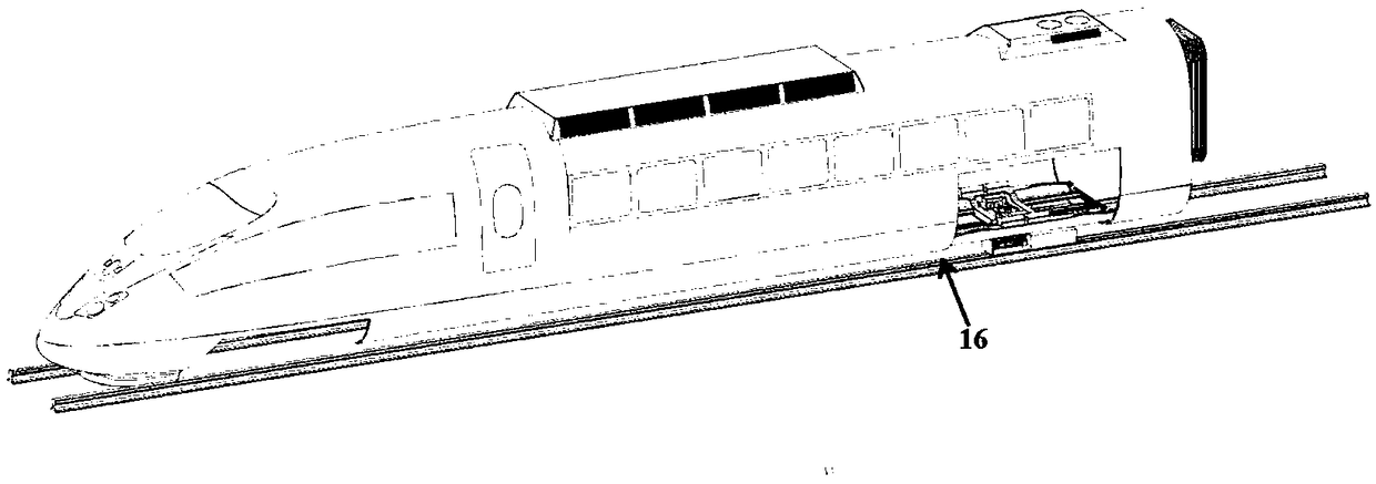
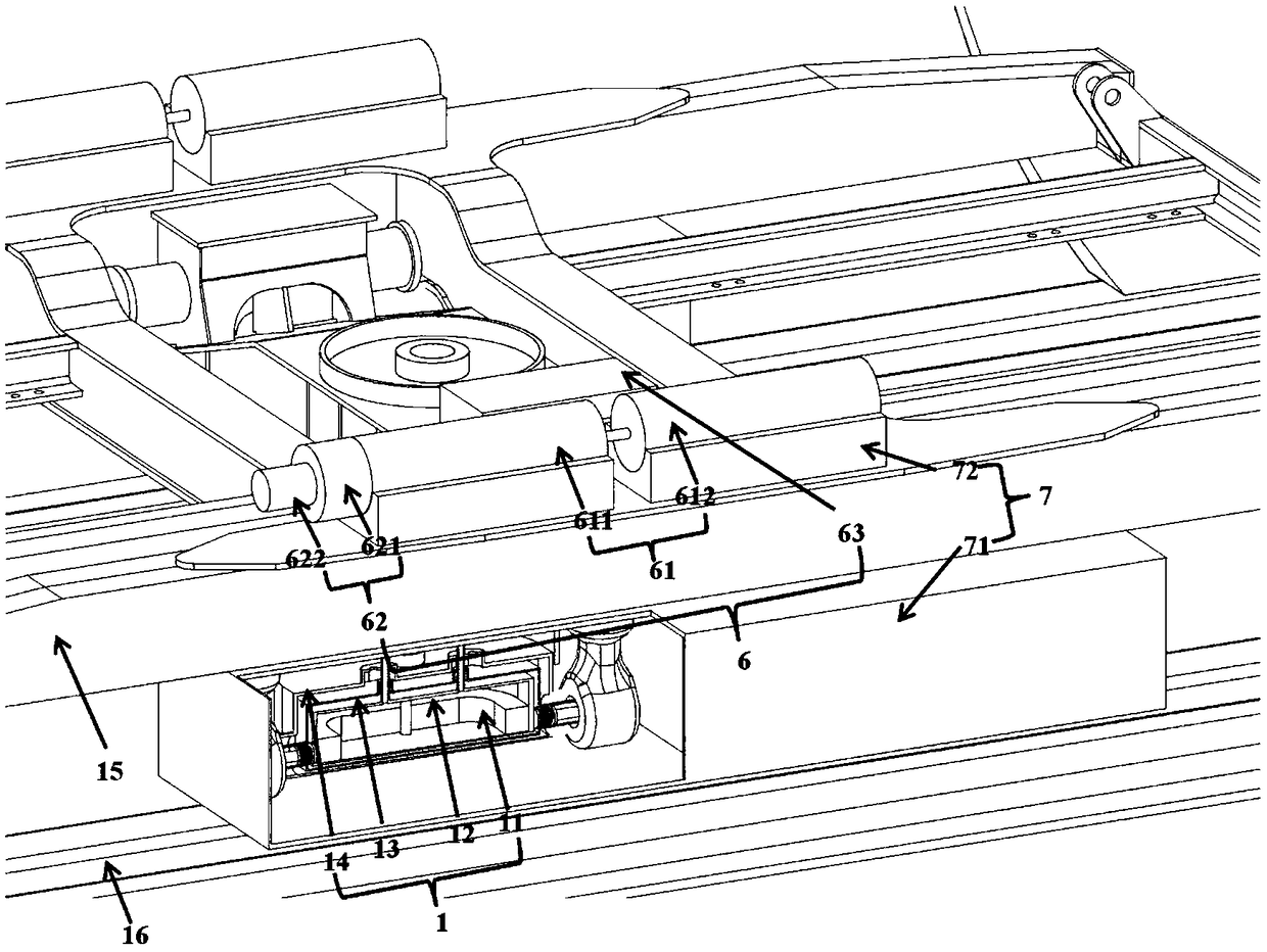
[0029] Embodiment 1: As shown in the figure, the superconducting eddy current brake for high-speed trains proposed by the present invention mainly includes a superconducting magnet unit 1, a low-temperature refrigeration unit 6 and a connection unit 7, and the superconducting eddy current brake for high-speed trains includes two The superconducting magnet unit 1 is bound on the bogie 15 through the connection unit 71 . The superconducting magnet unit 1 is located directly above the guide rail 16 of the high-speed train, and retains a certain air gap, and the superconducting magnet unit 1 and the two guide rails 16 below generate an eddy current effect to produce an eddy current effect that is consistent with the direction of travel of the high-speed train. opposite braking force.

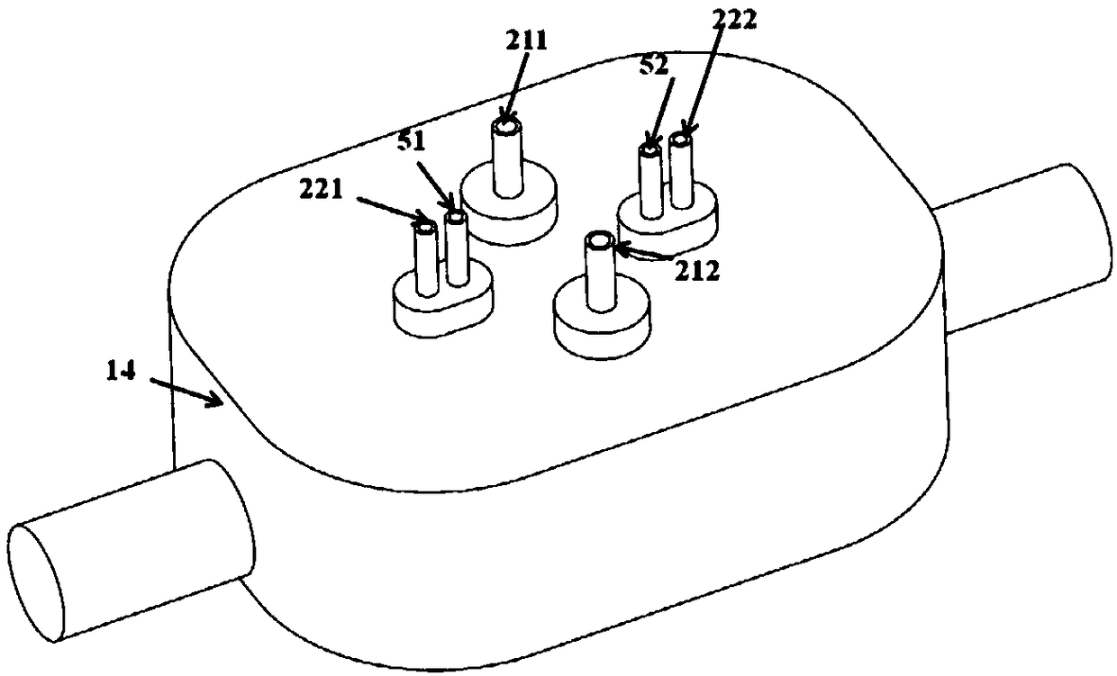
[0030] Specifically, each of the two superconducting magnet units 1 includes a pair of superconducting coils 11 to form alternating N and S poles.

[0031] Specifically, the superconducting magnet ...

specific Embodiment approach 2

[0048] Embodiment 2: This embodiment differs from Embodiment 1 in that: the material of the superconducting coil is a high-temperature superconducting wire, block or strip, and other parameters are the same as Embodiment 1.


PUM


Abstract

The invention discloses a superconducting eddy current brake for a high-speed train. The superconducting eddy current brake comprises a pair of superconducting magnet units forming alternating N and Spoles and a low-temperature refrigeration unit. A superconduct magnet unit is fixedly installed at that bottom of the high-speed train bogie and is provide with an air gap between the superconductingmagnet unit and the top surface of the guide rail under the bogie; a low-temperature refrigeration unit is installed on that bogie of the high-speed train; each superconducting magnet unit comprisesa superconducting container, wherein the superconducting container comprises a coil box, a cold screen and a dewar which are nested from the inside to the outside in sequence; the coil box is filled with liquid helium; the coil box is provided with a superconducting coil immersed in the liquid helium; the cold screen is in a high vacuum environment; and liquid nitrogen flow pipes are densely distributed on the outer wall of the cold screen. The superconducting eddy current brake not only meets the braking effect of high-speed operation, but also meets the requirements of lightweight, energy saving and emission reduction of high-speed train.

Description

technical field [0001] The invention belongs to the technical field of locomotive braking, in particular to the braking technology of high-speed trains. Background technique [0002] At present, the braking methods of high-speed trains mainly include pad brakes, disc brakes, and electric brakes. The above brakes are all adhesive brakes, and their active effect is affected by the adhesion performance between the wheel and rail, that is, the friction coefficient of the wheel and rail, and the mechanical friction pressure of brake discs, brake pads and other components is large, and the loss is serious. For a given train and operating route, the wheel-rail friction coefficient is mainly affected by the following factors: 1. Rail surface conditions: harsh natural conditions such as rain, snow, ice, and fallen leaves will greatly reduce the wheel-rail friction coefficient; 2. Train speed: wheel The rail friction coefficient decreases rapidly with the increase of train speed. The...

Claims


Application Information

Patent Timeline
Patent Type & Authority Applications(China)
IPC IPC(8): B60L7/28
CPCB60L7/28B60L2200/26H02K49/02Y02T10/64B60L13/04B60L13/10
Inventor 方超卫靖宋云涛戴文华
Owner HEFEI INSTITUTES OF PHYSICAL SCIENCE - CHINESE ACAD OF SCI
Why Eureka
Try Eureka