Irrigation and drainage system and construction method of water delivery canal

A drainage system and channel technology, applied in irrigation pipelines, artificial waterways, water conservancy projects, etc., can solve the problems of inconvenient irrigation water, drying up, construction waste, etc.

Inactive Publication Date: 2019-01-01
汇杰设计集团股份有限公司
View PDF3 Cites 5 Cited by
  • Summary
  • Abstract
  • Description
  • Claims
  • Application Information

AI Technical Summary

Problems solved by technology

However, many places in our country have undulating topography and uneven distribution of water resources.
Especially in high places, irrigation water is extremely inconvenient, which seriously affects agricultural production. Therefore, the construction of water conservancy projects is an important means to ensure agricultural production, maintain production and increase income.
At present, there are a large number of reservoirs built in our country, but they generally adopt the method of natural water storage, which uses the fluidity of water to automatically collect and accumulate in low-lying reservoirs. However, in the face of long-term drought, the water in the reservoirs cannot be replenished. , often dry up, unable to meet agricultural production
[0003] At the same time, water conservancy projects built in rural areas are often unreasonable in design and substandard in quality due to insufficient planning. Water conservancy buildings have collapsed, hollowed out, and leaked under the erosion of water for a long time, and even dams have collapsed in severe cases. seriously affect the personal and property safety of downstream residents and cause serious construction waste

Method used


Image

  • Irrigation and drainage system and construction method of water delivery canal
  • Irrigation and drainage system and construction method of water delivery canal
  • Irrigation and drainage system and construction method of water delivery canal

Examples


Embodiment Construction

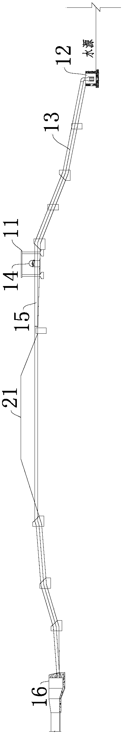
[0050] Such as figure 1As shown, an irrigation and drainage system includes water source engineering and irrigation and drainage engineering in turn, and the water source engineering includes a pumping station and an upstream reservoir;

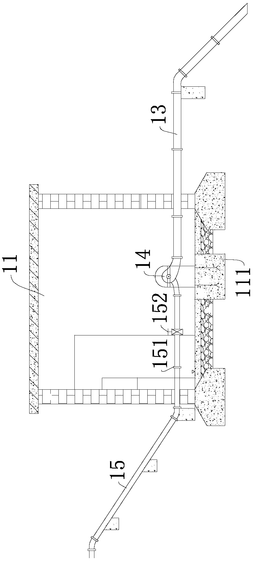
[0051] Such as figure 2 As shown, the pumping station includes a pump room 11 and a water inlet pool 12, a water inlet pipe 13, a water pump 14, an outlet pipe 15 and an outlet pool 16 connected in sequence, and the outlet pool 16 is located in the reservoir; the water inlet pool 12 is close to the water source and communicated with the water source. The water inlet of the pool 12 is provided with a trash rack; the pump room 11 is provided with a water pump base 111 on which the water pump 14 is fixedly mounted, and the water pump 14 is connected to the driving motor through transmission.

[0052] The water inlet pool 12 is close to the water source and communicates with the water source through the water inlet. The bottom of the water inle...


PUM


Abstract

The invention discloses an irrigation and drainage system which comprises a water source project and an irrigation and drainage project. The water source project comprises a reservoir and a pump station for supplying water to the reservoir, the reservoir comprises a retaining dam, a spillway, and a water bypass, the water inlet end of the spillway is communicated with the reservoir, the water outlet end of the spillway is provided with a stilling basin, the stilling basin is located at the bottom of the retaining dam, the water discharge duct is located at the lower part of the retaining dam,the water inlet end of the water discharge duct is communicated with the reservoir, and the water outlet end of the water discharge duct is communicated with the stilling basin after passing through the retaining dam; the irrigation and drainage project comprises a water conveyance channel, wherein the water conveyance channel comprises a main canal and a branch canal for irrigation and drainage;the water inlet of the main canal is communicated with a stilling basin; the water inlet of the branch canal is communicated with the main canal; and the branch canal is connected with a point to be irrigated. The invention has the advantages of reasonable design, long service life and high comprehensive economic benefit of flood control irrigation. The invention is applied to the technical fieldof water conservancy construction.

Description

technical field [0001] The invention relates to the technical field of water conservancy engineering, in particular to a construction method for an irrigation and drainage system and a water delivery channel. Background technique [0002] my country is a large agricultural country, and agriculture has always been related to the economic lifeline of the people. Agricultural production requires a lot of water. However, many places in our country have undulating topography and uneven distribution of water resources. Especially in high places, the water for irrigation is extremely inconvenient, which seriously affects agricultural production. Therefore, the construction of water conservancy projects is an important means to ensure agricultural production and increase income. At present, there are a large number of reservoirs built in our country, but they generally adopt the method of natural water storage, which uses the fluidity of water to automatically collect and accumulat...

Claims


Application Information

Patent Timeline
Patent Type & Authority Applications(China)
IPC IPC(8): E03B5/00E02B8/06E02B5/00E02B13/00E02B5/08E02B8/04E02B5/02
CPCE02B5/00E02B5/02E02B5/08E02B8/04E02B8/06E02B13/00E03B5/00Y02A20/20
Inventor 佘凯彭秀莲李为罗坚黄鸿君
Owner 汇杰设计集团股份有限公司
Why Eureka
Try Eureka