Electronic padlock

A padlock and electronic technology, applied in the field of locks, can solve problems such as complex structure and easy failure, and achieve the effect of simple and compact structure, reduced manufacturing cost, and simple locking and unlocking operations

Inactive Publication Date: 2019-01-01
SMART ELECTRONICS IND DONG GUAN +1
View PDF7 Cites 2 Cited by
  • Summary
  • Abstract
  • Description
  • Claims
  • Application Information

AI Technical Summary

Problems solved by technology

[0004] As another example, Chinese patent document CN102444328A discloses an electronic padlock, which uses the principle of electromagnetic induction to insert an electronic key into the keyhole, and after the electronic control board verifies the ID of the key, it energizes the coil in the lock cylinder, and the coil generates a magnetic field to control the lock. The sliding magnetic block moves, and the function of opening and closing the lock is realized through the movement of the sliding magnetic block. However, the use of electromagnetic principles to unlock and unlock requires the use of torsion spring torque, which obviously has the disadvantages of complex structure and easy failure.

Method used


Image

  • Electronic padlock
  • Electronic padlock
  • Electronic padlock

Examples


Embodiment Construction

[0029] The present invention will be further described in detail below in conjunction with the accompanying drawings and specific embodiments.

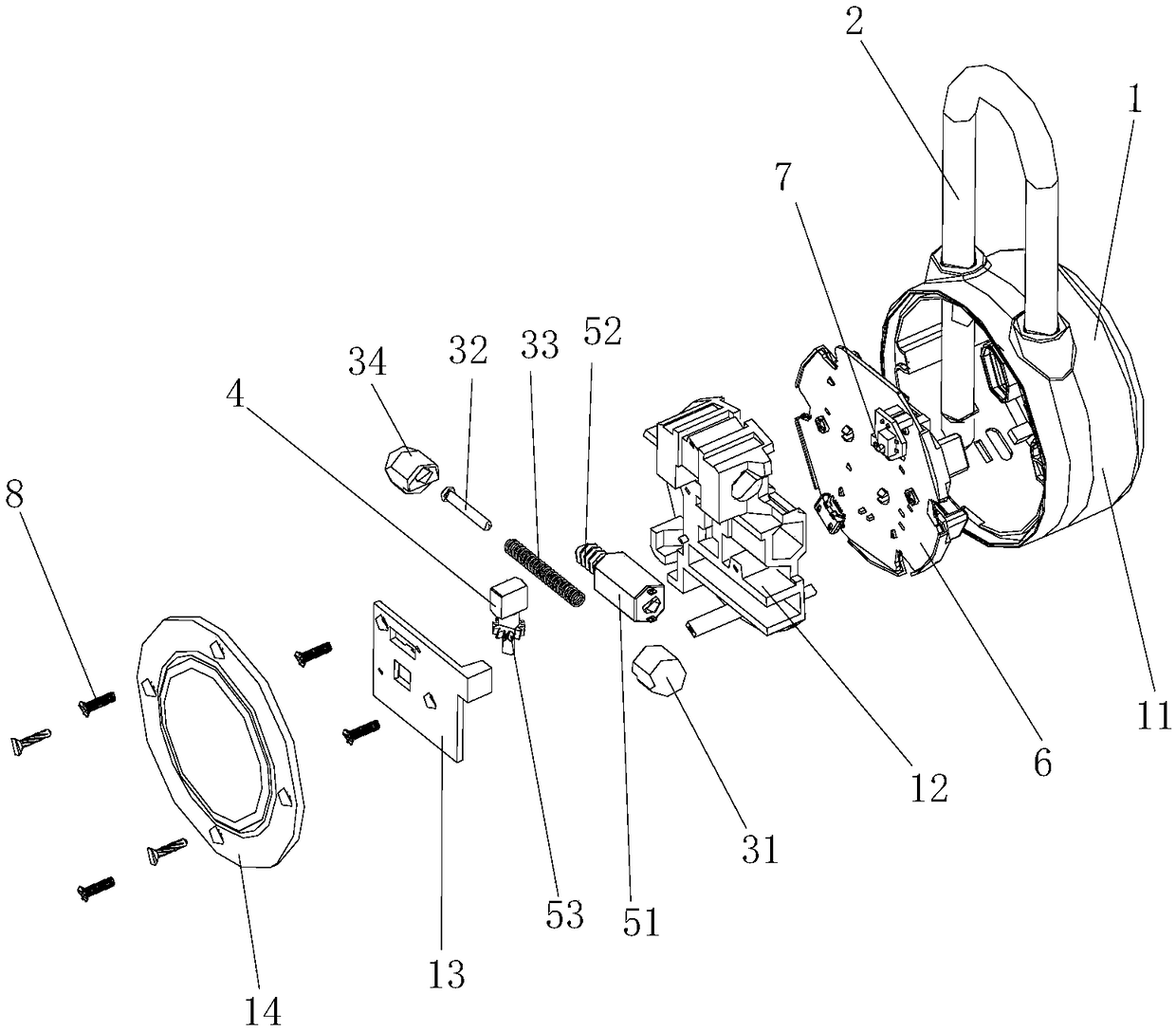
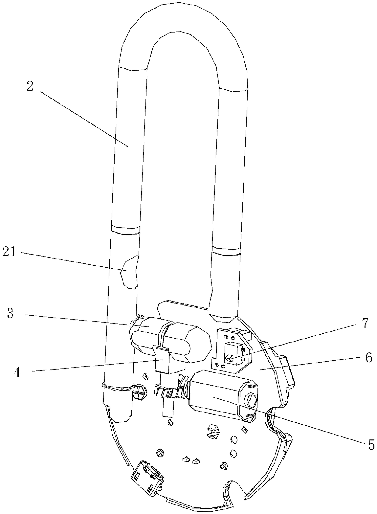
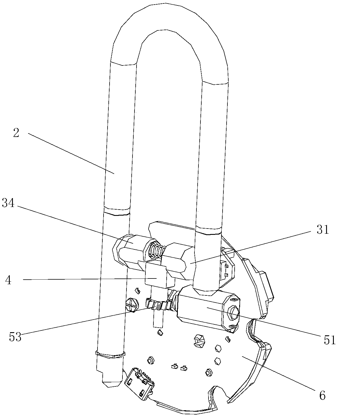
[0030] Figure 1 to Figure 3 The first embodiment of the electronic padlock of the present invention is shown. The electronic padlock of this embodiment includes a lock body 1 and a lock hook 2. One end of the lock hook 2 is installed on the lock body 1, and the lock hook 2 can be arranged relative to the lock body. 1 moves up and down, the two inner parts opposite to the lock hook 2 are provided with arc-shaped grooves 21, the electronic padlock also includes a locking part 3, a locking block 4 and an electronically controllable driving part 5, and the locking part 3 is a retractable structure And both ends are arc-shaped protrusions 31 that can cooperate with the arc-shaped groove 21. When locked, the two arc-shaped protrusions 31 cooperate with the arc-shaped groove 21 so that the lock hook 2 cannot move up and down. In the unlock...


PUM


Abstract

The invention discloses an electronic padlock. The electronic padlock comprises a lock body and a latch hook; one end of the latch hook is arranged on the lock body, and the latch hook can be moved relative to the lock body up and down; the two opposite inner sides of the latch hook are each provided with an arc-shaped groove, and the electronic padlock further comprises a locking part, a lockingblock and a driving part which can be controlled electronically; the locking part is of a telescopic structure, and the two ends of the locking part are both arc-shaped lug bosses which can be matchedwith the arc-shaped grooves; in the locking state, the two arc-shaped lug bosses are both matched with the arc-shaped grooves so that the latch hook can not be moved up and down; in the unlocking state, the two arc-shaped lug bosses can be moved towards each other so that the arc-shaped lug bosses are separated from the arc-shaped grooves when the latch hook is pulled upwards; and the locking block can be driven by the driving part to act so that the locking part is switched between the locking state and the unlocking state. The electronic padlock has the advantages of the simple structure, convenient operation of locking and unlocking, low power of the driving part and the like.

Description

technical field [0001] The invention relates to a lockset, in particular to an electronic padlock with simple structure, convenient locking and unlocking operation, and low driving power. Background technique [0002] Padlock is a kind of lock that is widely used. It usually includes a lock body, a shackle, a locking piece and an upper unlocking mechanism that drives the locking piece to lock or unlock. The shackle is installed on the lock body, and the upper unlocking mechanism drives the locking piece to lock. Or unlock the shackle, the traditional padlock is manually unlocked by the key, which has poor security and intelligence, and the electronic padlock uses electronic signal control to realize unlocking or unlocking, which is convenient and flexible to use and has higher security, but the upper unlocking mechanism needs to be locked in the control component In order to ensure the reliability and stability of the action, more matching components are required, resulting ...

Claims


Application Information

Patent Timeline
Patent Type & Authority Applications(China)
IPC IPC(8): E05B67/00E05B67/06E05B67/22E05B47/00
CPCE05B47/0012E05B67/00E05B67/06E05B67/063E05B67/22
Inventor 郑犁
Owner SMART ELECTRONICS IND DONG GUAN
Why Eureka
Try Eureka